MITICA is the prototype of the neutral beam injector for hydrogen or deuterium particles and is an integral part of the NBTF (Neutral Beam Test Facility) project.
The injector will be used to heat the plasma of ITER, THE FIRST NUCLEAR FUSION REACTOR currently under construction in Cadarache, France.
To achieve this, it must be capable of producing a beam of neutral hydrogen or deuterium particles with sufficient speed and energy to penetrate the reactor.
NBI heating system of ITER
To accelerate the hydrogen or deuterium atoms so they can reach the required speed and energy levels, MITICA must first ionize them — that is, give them a negative charge.
Once accelerated, it must then neutralize them (i.e., remove the negative charge) so they can reach the core of ITER without interference.
How does MITICA manage to do all this?
Click the buttons
to explore the system step by step:
The NBTF plant
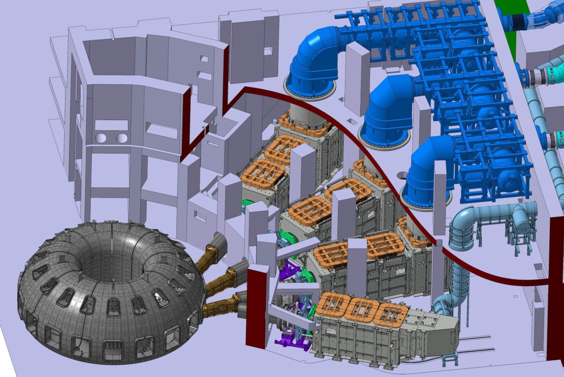
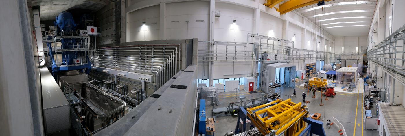
MITICA is located in Building 1, the large experimental hall of the NBTF facility, alongside SPIDER, the prototype of the negative ion source.
Like SPIDER, MITICA is also placed inside a reinforced concrete bunker with 180 cm thick walls which, once sealed, protects against neutron radiation and X-rays produced during operation.
This ensures safe access to the experimental area.
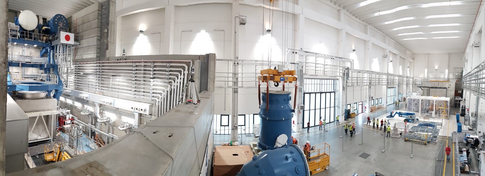
Building 1 of the NBTF facility – on the left, from above, MITICA open bunker
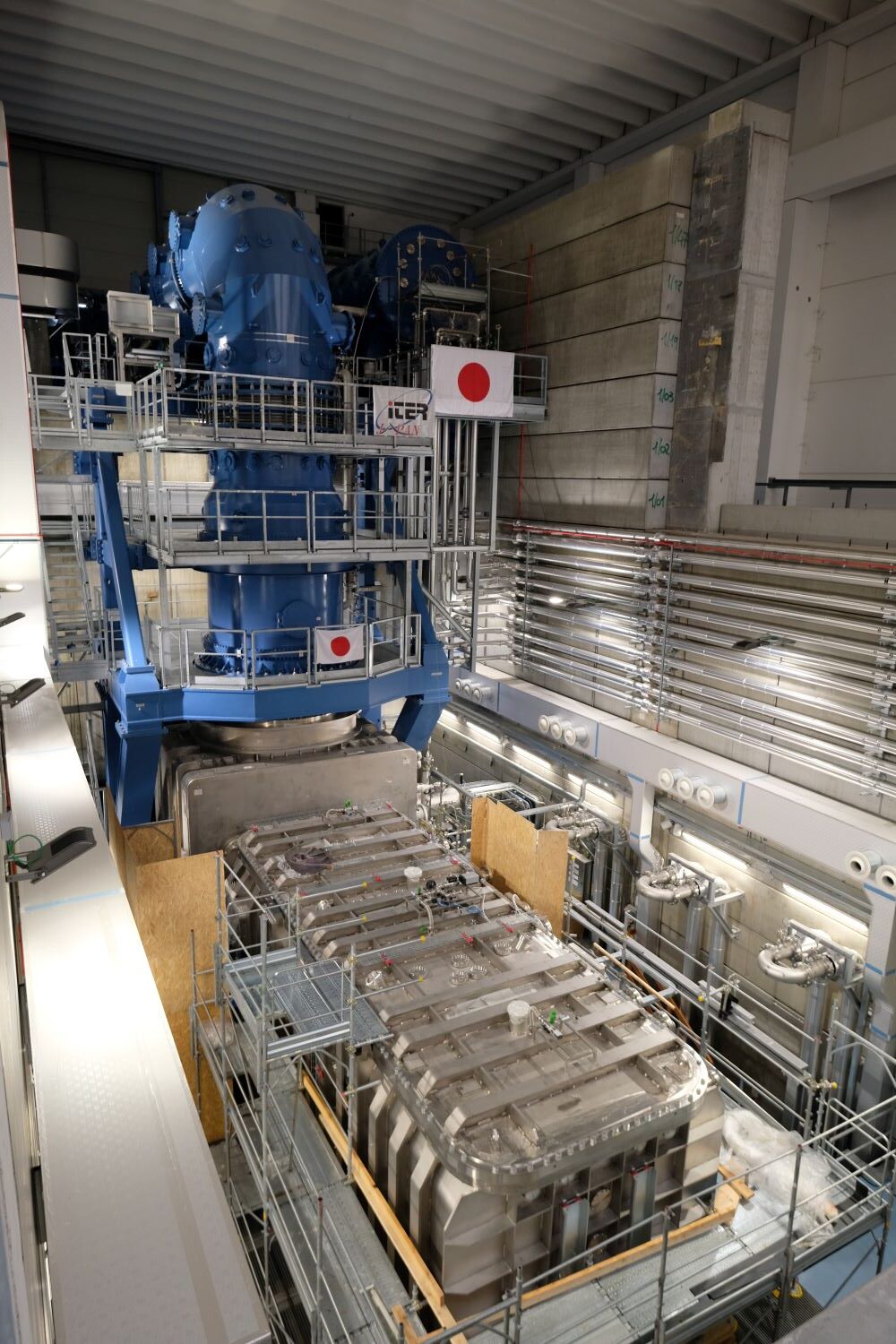
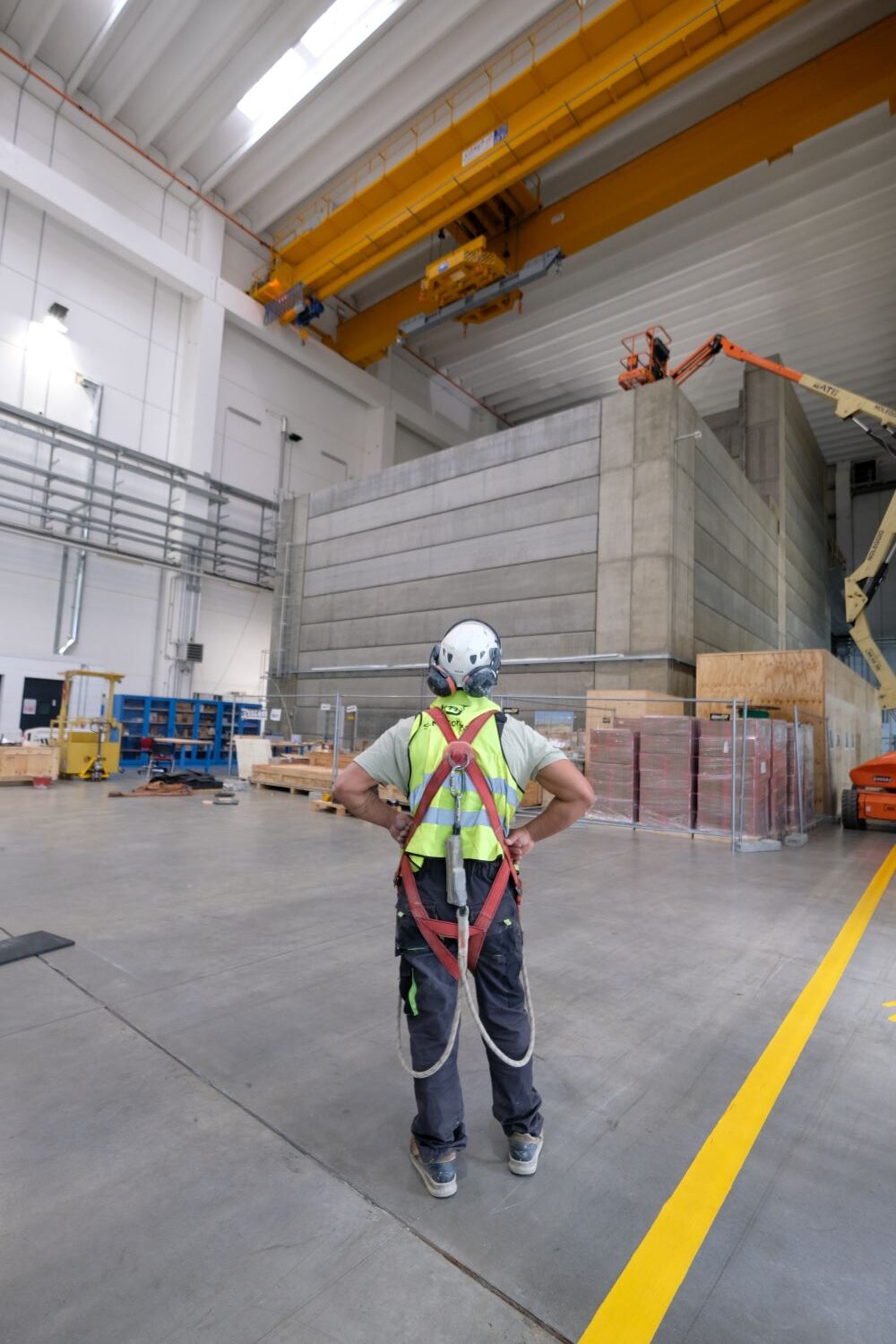
On the left, MITICA – In the center, MITICA from above – On the right, MITICA open bunker under construction
Radiation is a phenomenon in which energy is emitted and propagated by a substance.
It can occur in the form of particles, such as neutrons — uncharged particles found in the nucleus of atoms (neutron radiation) — or in the form of waves, like X-rays.
In both cases, energy is transmitted through space without the need for any supporting material medium.
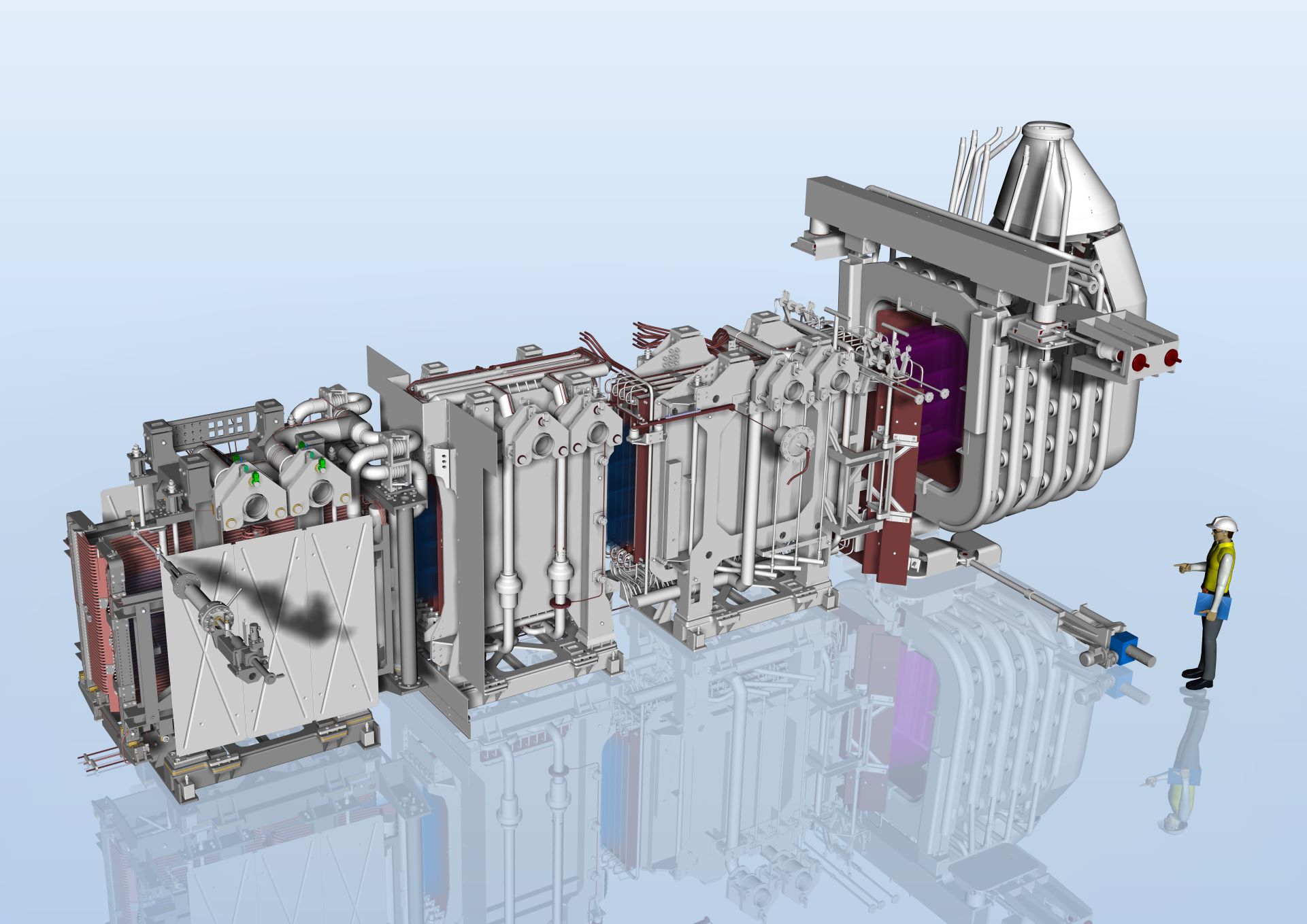
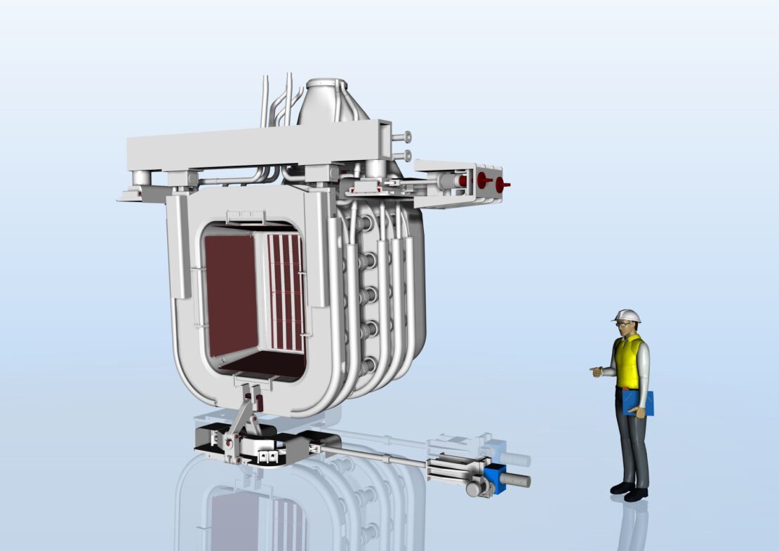
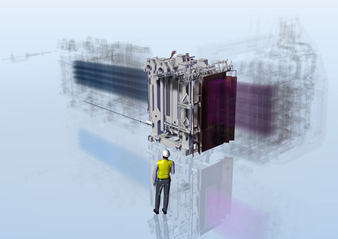
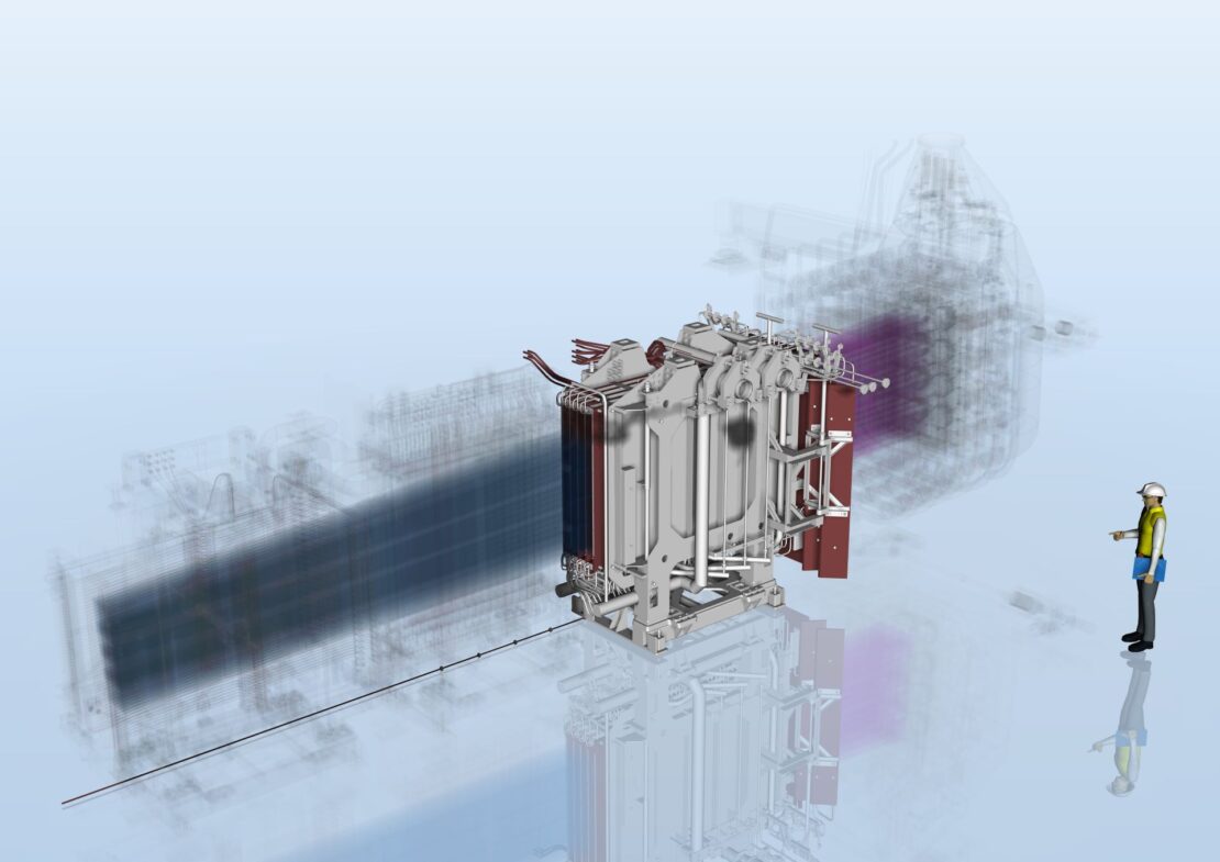
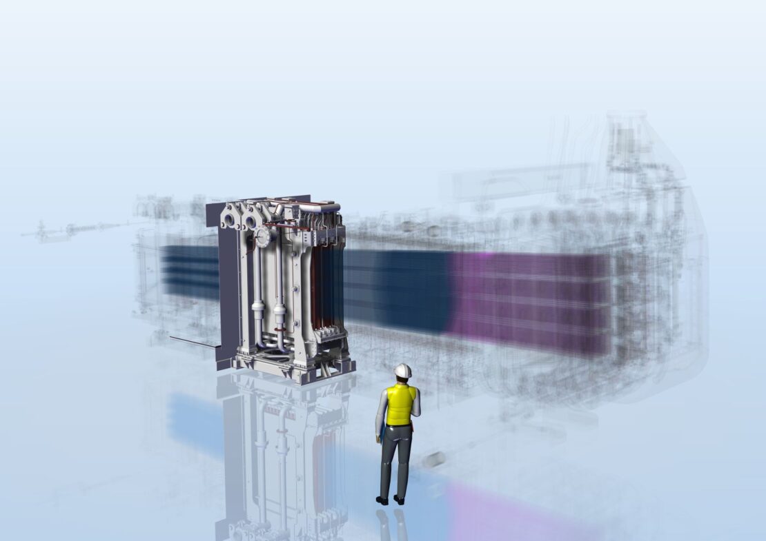
The heart of MITICA — known by researchers as the “beam line” — is housed inside a large stainless steel box measuring 15m x 5m x 5m, called the vacuum vessel, where ultra-high vacuum can be generated.
It consists of four main components (see figure below):
the Beam Source, which generates the beam of negative ions
the Neutraliser and Electron Dump, which neutralizes most of the negative ions, making them neutral
the Residual Ion Dump (RID), which completes the neutralization of any remaining charged ions
the Calorimeter, which intercepts and analyzes the neutral particle beam, destined to heat the core of the fusion reactor once operational.
Click on the interactive rendering below, to identify the beam line components
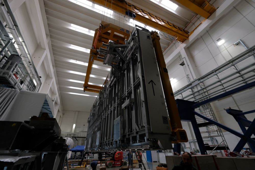
The Vacuum Vessel is a stainless steel parallelepiped measuring 15m x 5m x 5m, made of two modules in 304L stainless steel: the Beam Source Vessel (BSV) and the Beam Line Vessel (BLV), described below.
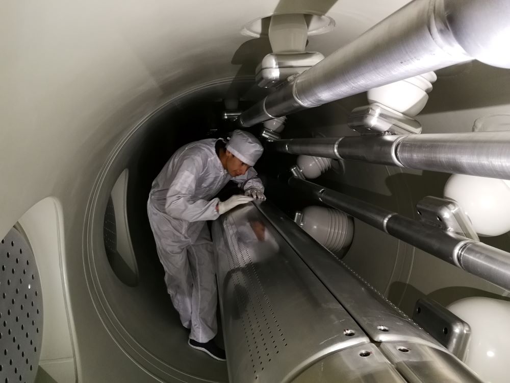
In-vessel view
304L stainless steel is part of the austenitic stainless steel family. Like all steels, it is an alloy composed of Iron (Fe) and Carbon (C), but it also contains a percentage of Chromium (Cr) (between 18% and 20%) and Nickel (Ni) (between 8% and 11%).
The addition of these elements allows for passivation — a process by which a protective layer forms on the surface of the material through reaction with oxygen in the air, making it resistant to corrosion
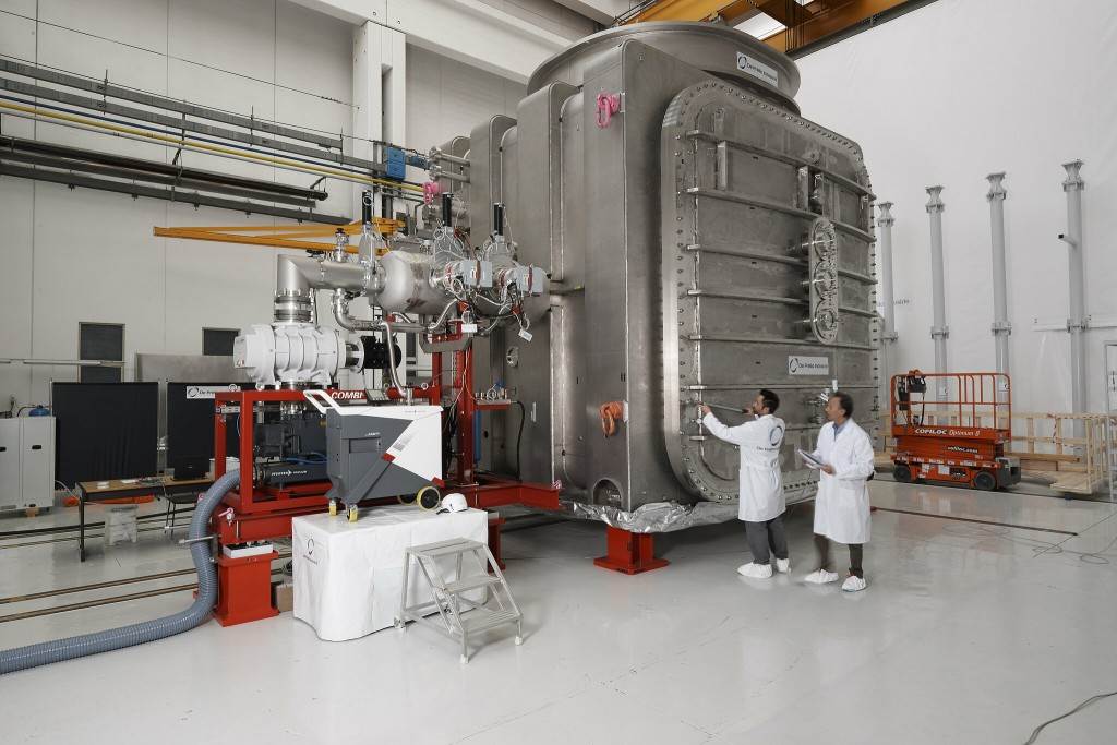
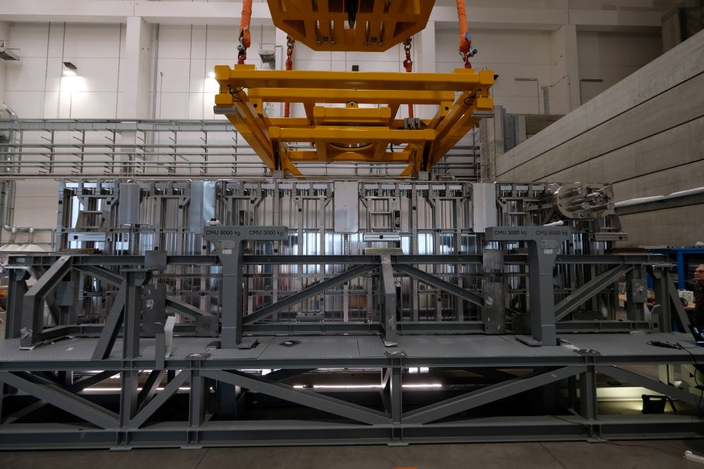
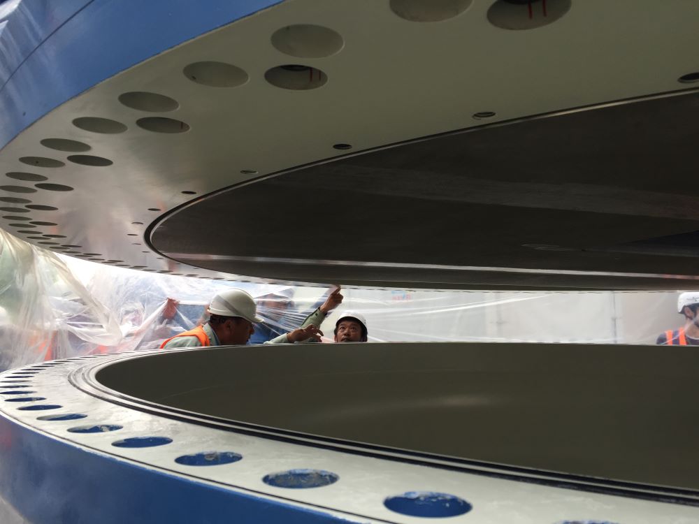
The first module, the Beam Source Vessel (BSV), houses the beam source. It has the shape of a cube with 5-meter edges and weighs 47 tons.
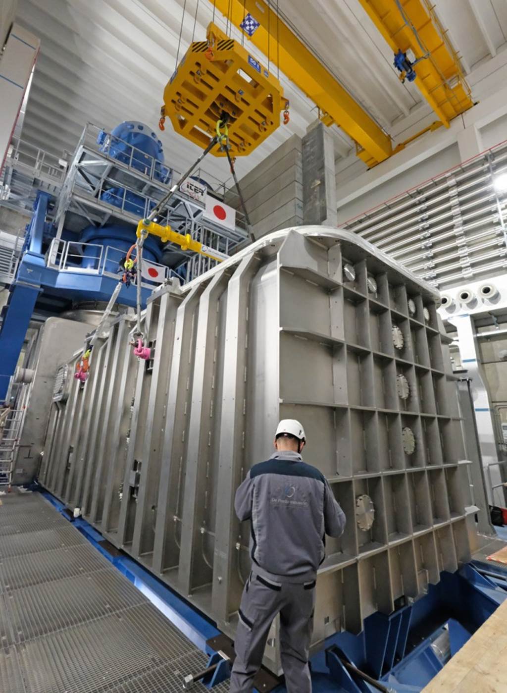
The second module is the so-called Beam Line Vessel (BLV).
With its impressive dimensions — 4.5 meters in height, 4.5 meters in width, 11 meters in length — and a mass of 49 tons, it contains all the components through which the beam passes.
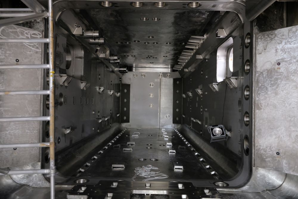
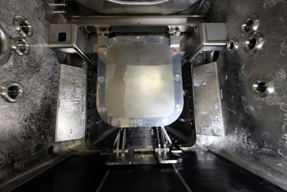
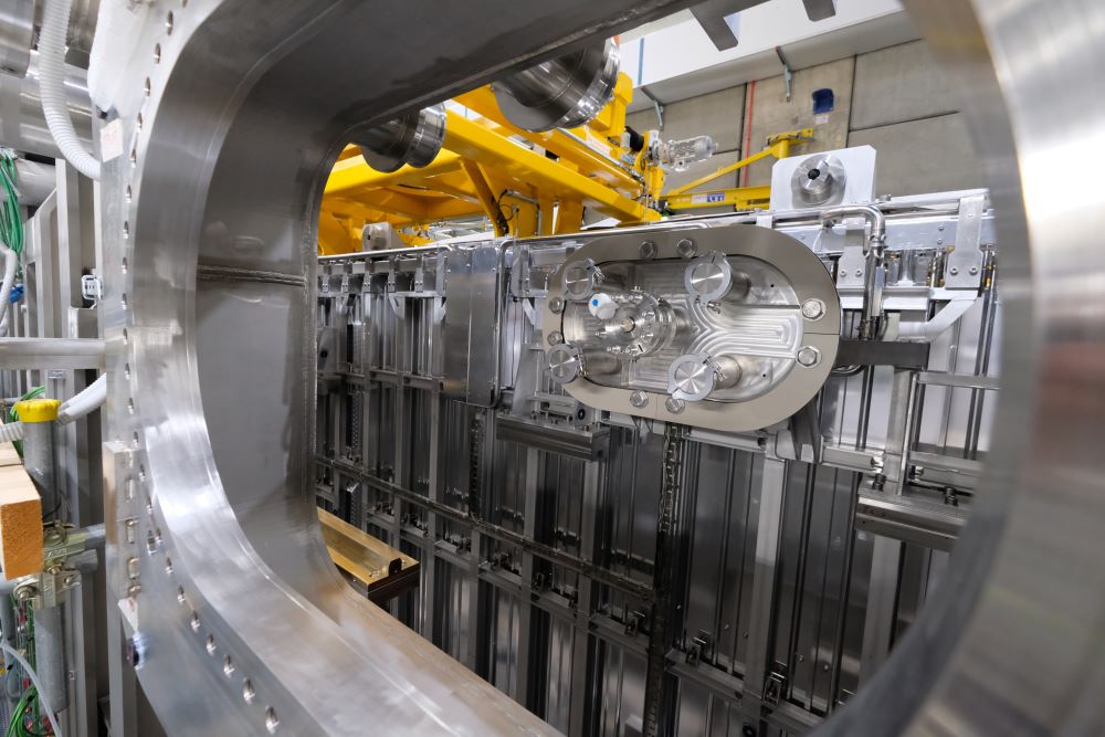
The interior of MITICA’s vessel
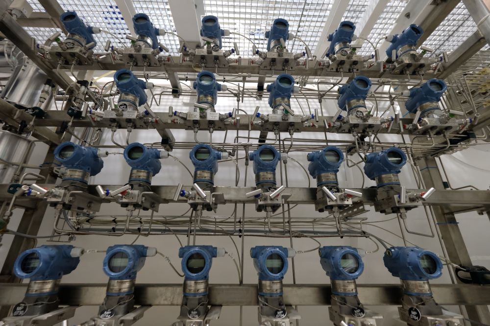
On the side walls of the vacuum vessel, there are openings. Some allow the insertion of MITICA diagnostic instruments, while others provide connections to three other essential systems for the injector’s operation:
To maintain the vacuum inside the vessel, cryopumps are used—pumps that operate at extremely low temperatures.
They measure 8 meters in length, 2.5 meters in width, and 40 centimeters in depth.
They are mounted inside the vessel along the two vertical side walls, and due to their size, they cover almost the entire area.
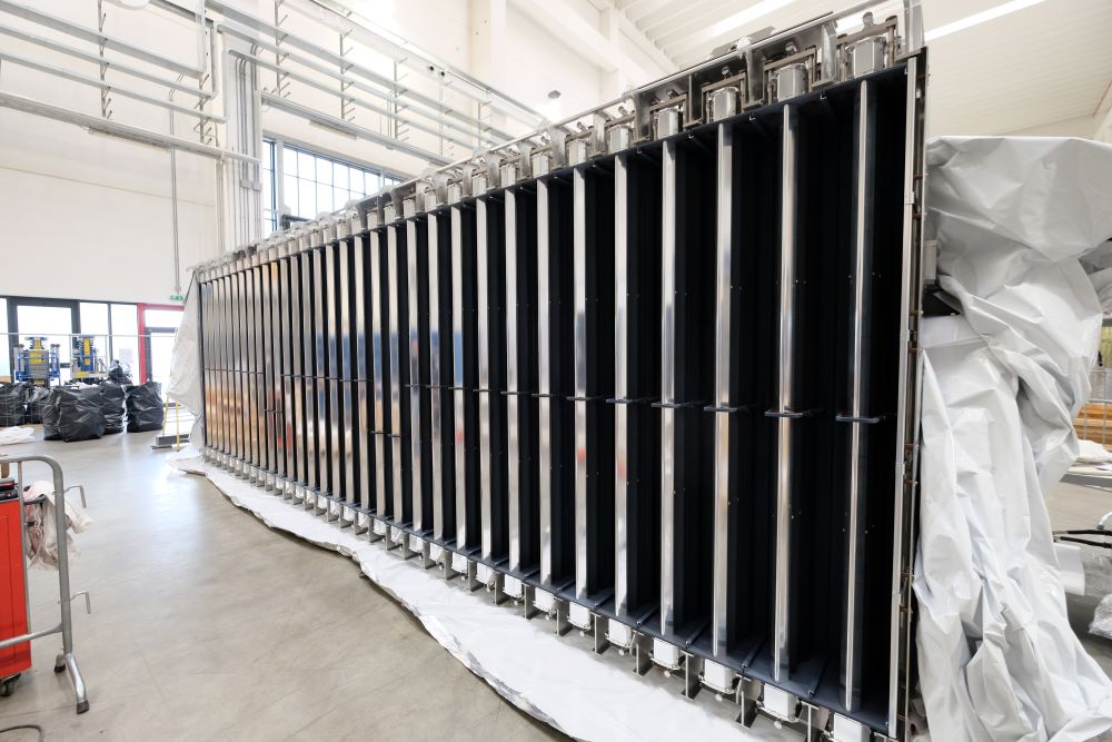
They are made of steel and aluminum and are partially coated with an absorbent material derived from coconut shells.
When cooled to about –268°C (approximately 5 K), this material is able to absorb hydrogen molecules present inside the vessel, helping to achieve the desired vacuum.
Once saturated, it will be necessary to remove the trapped hydrogen to make it operational again. This will be possible by raising the temperature to around 100 K and extracting the released gas
The initial pressure before gas injection is 10-7mbar.
QWhen MITICA is operating, a very small amount of gas is injected — to generate plasma — which raises the pressure to 10-5mbar.
1 bar corresponds to approximately 1 atmosphere.
1 mbar corresponds to one thousandth of an atmosphere.
10-7 mbar corresponds to ten-billionths of an atmosphere.
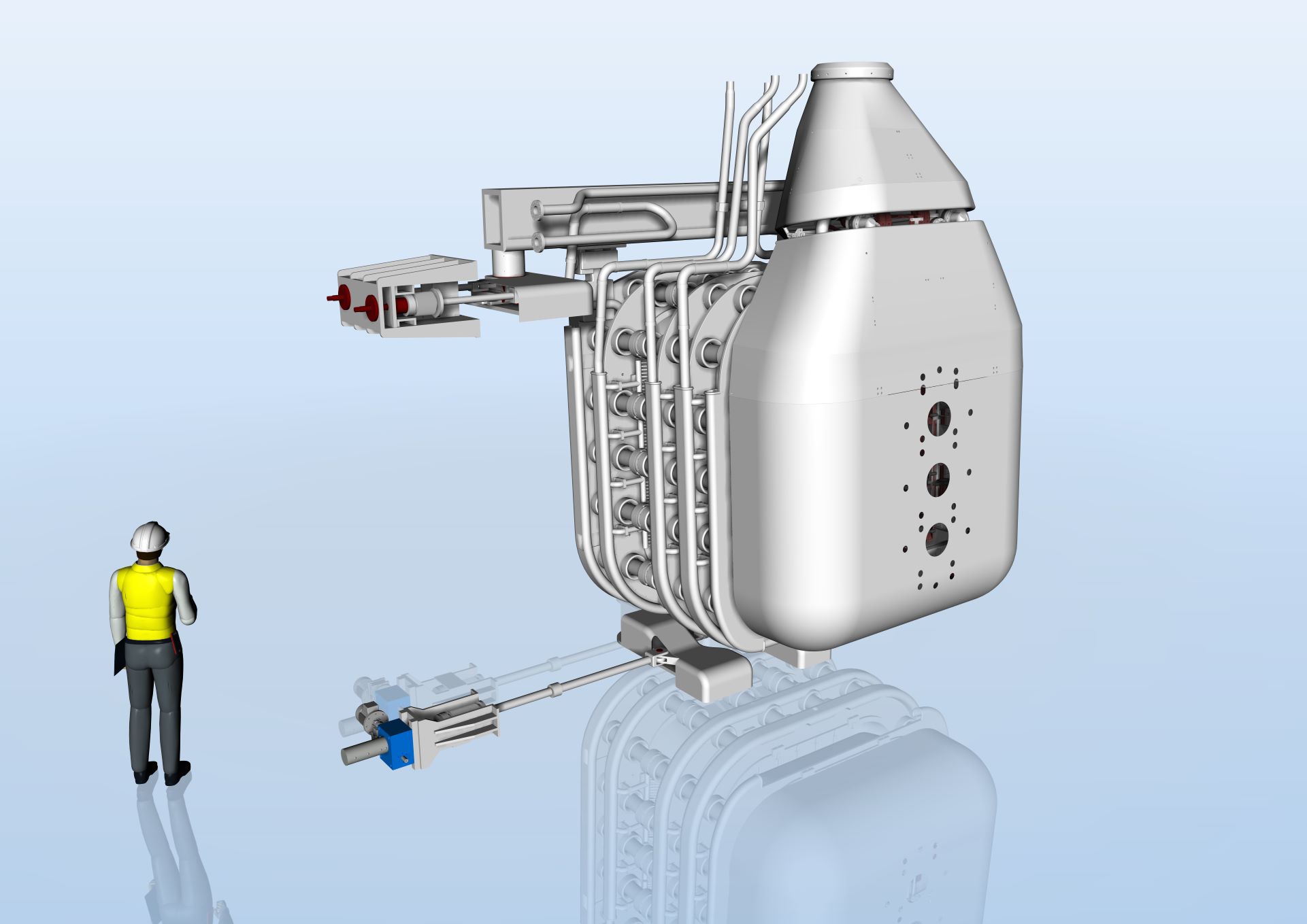
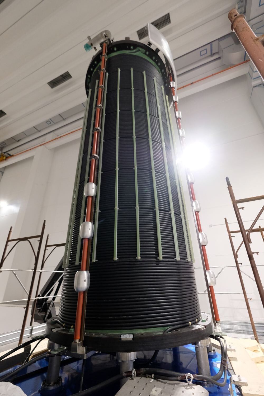
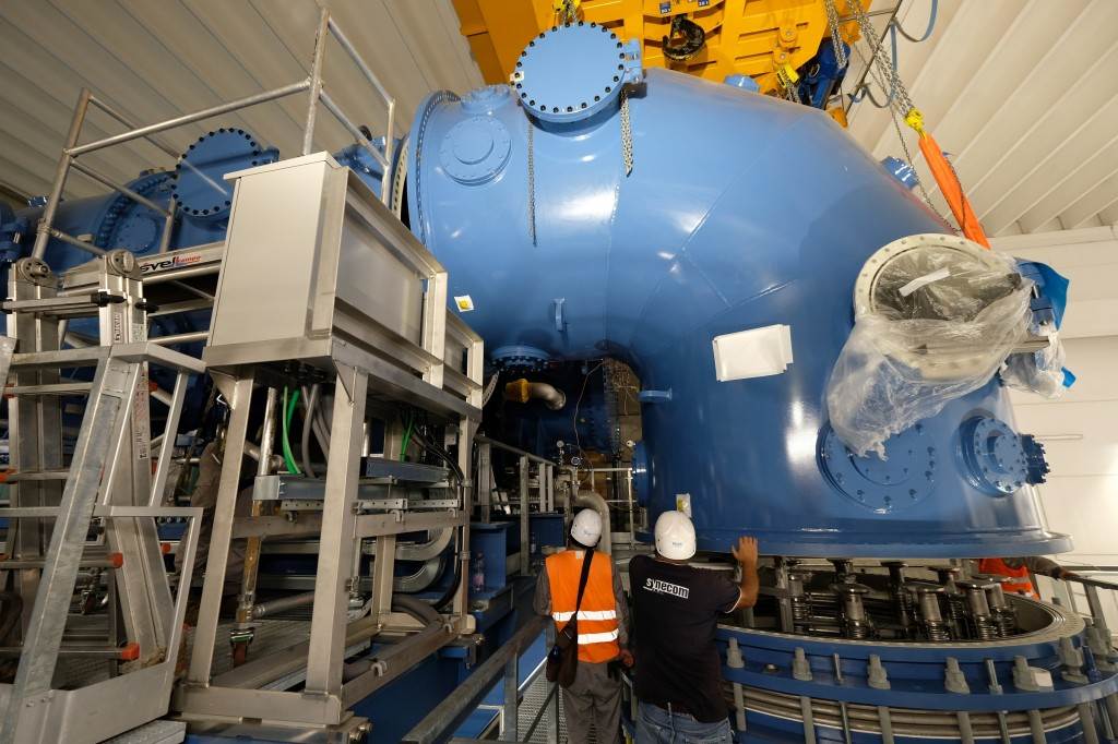
Inside the Beam Source Vessel (BSV) is MITICA’s Beam Source, the most critical component of the injector.
It measures 3m x 3m x 4.5m and weighs about 15 tons
The source consists of two parts, each dedicated to different functions:
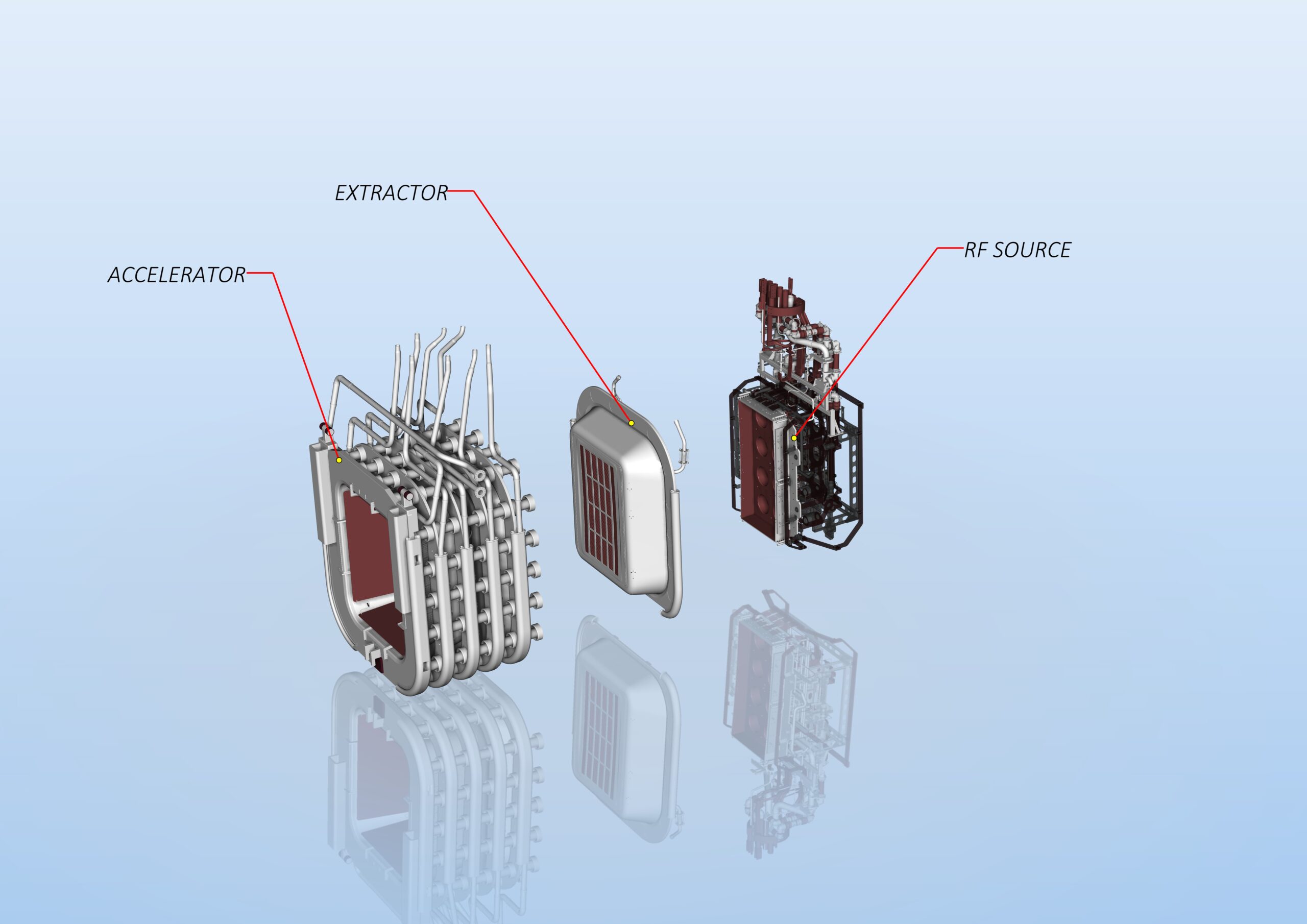
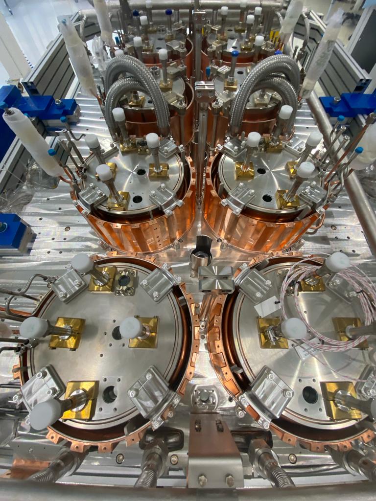
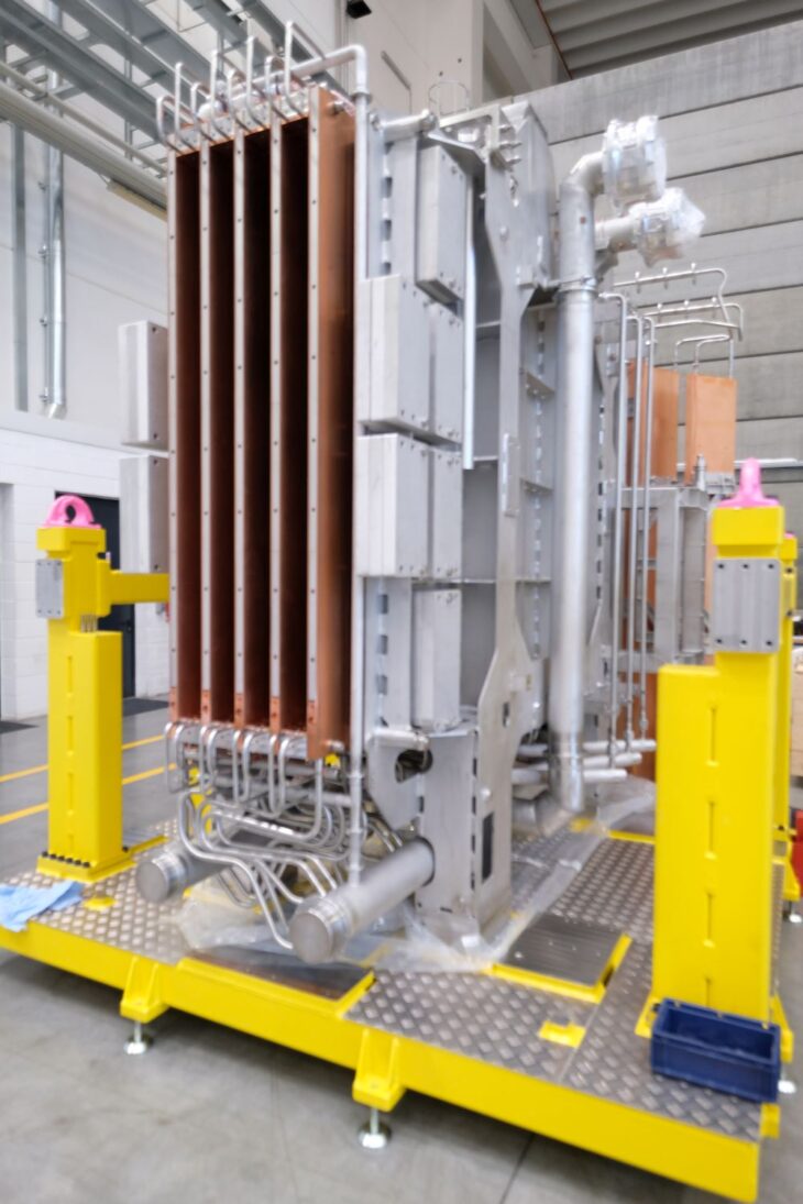
The Plasma Source (also called the RF Source) is equipped with 8 drivers, which are cylindrical chambers containing the gas (hydrogen or deuterium) that will be transformed into plasma.
Around each driver are copper tubes (coils) through which alternating current flows at a suitable frequency.
The alternating current flowing in the coils generates radiofrequencies capable of exciting the gas molecules inside the drivers, ionizing them and thus transforming the gas into a low-energy plasma mainly composed of negative ions, positive ions, and electrons.
The Plasma Source is electrically powered by the ISEPS system.
(Discover later what alternating current is)
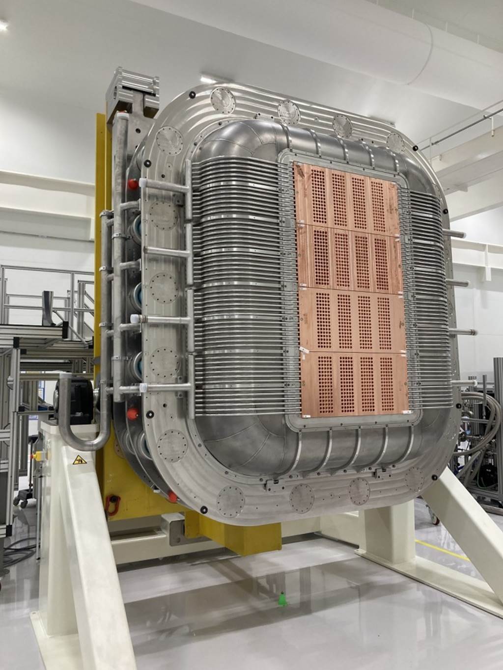
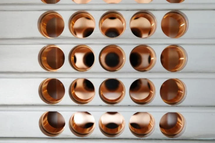
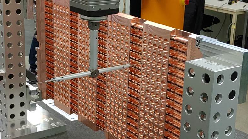
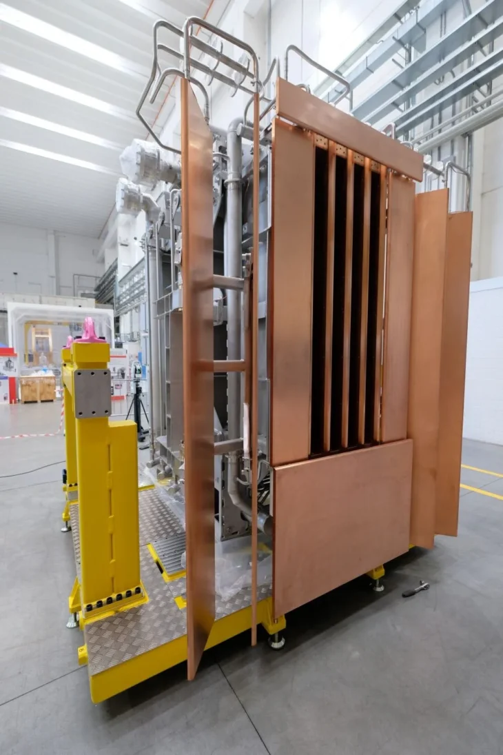
The second part of the source, dedicated to extracting and accelerating the negative ions that form the beam, consists of 7 perforated copper plates (grids) with 1280 precisely calibrated and properly aligned holes.
To increase the efficiency of the extraction operation, cesium is applied to the surface of the grids. (Discover later what cesium is used for)
The acceleration grids are electrically powered by the AGPS system.
Cesium is an alkaline metal that donates electrons. The electrons provided by cesium, once heated to a high temperature, increase the number of negative ions produced.
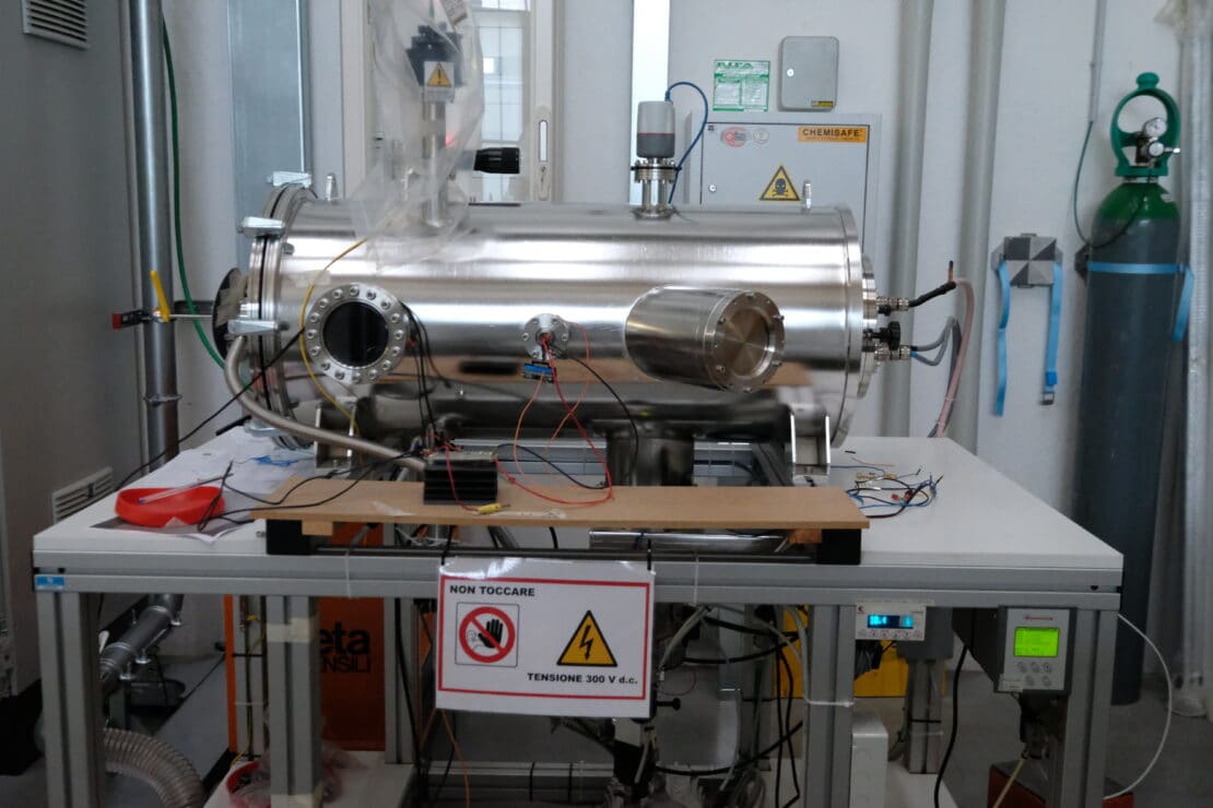
Discover the Caesium Test Stand
The grids are arranged parallel to each other and perpendicular to the beam.
In sequence, they are:
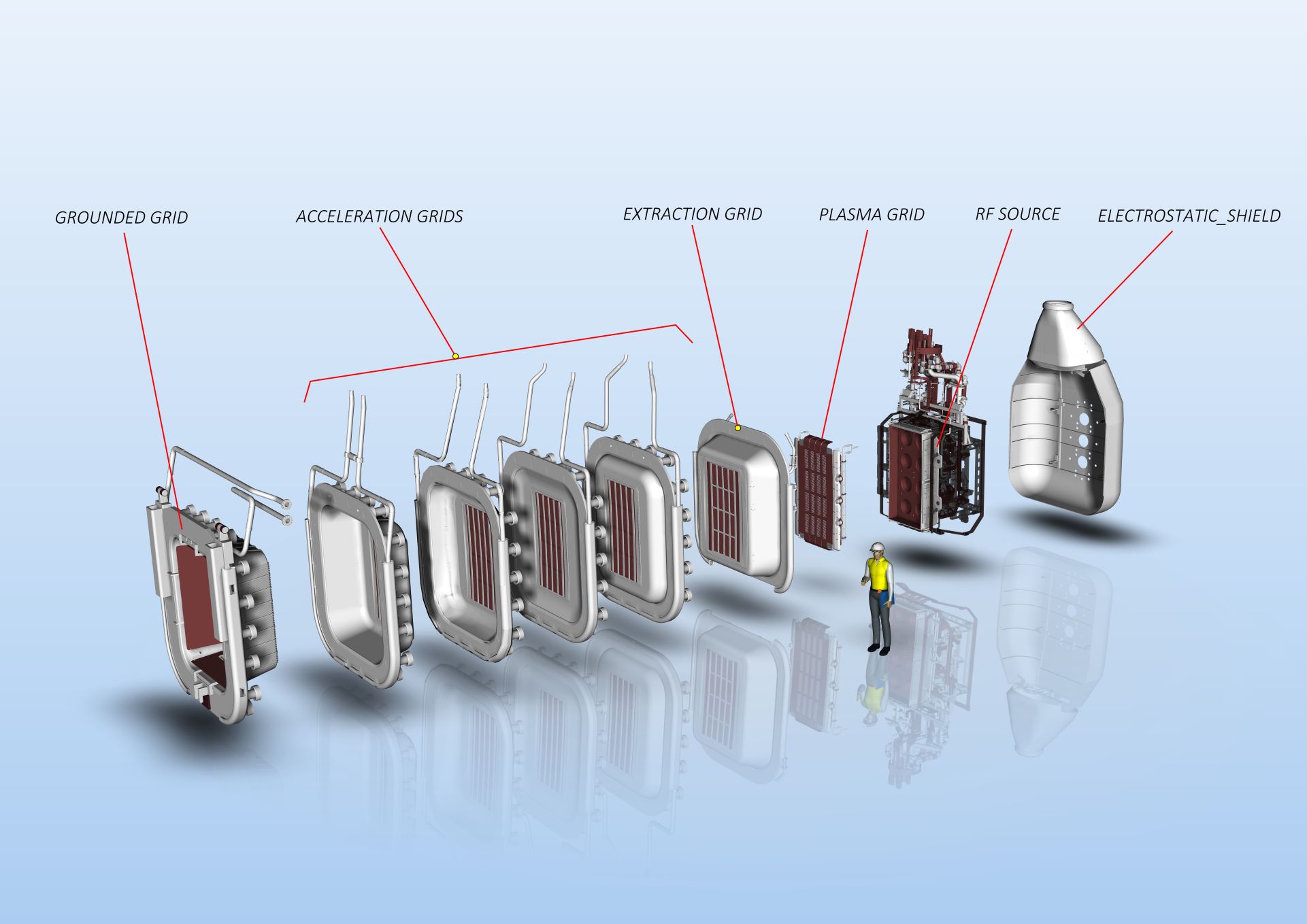
In detail:
Of all the charges present in the plasma produced by the eight drivers in the space before the plasma grid, only the negative ions are “channeled” by the extraction grid towards the following grids up to the grounded grid, generating the negative ion beam.
What accelerates these electrically charged atoms is the potential difference between the grids. Each grid is charged at an increasing electric potential provided by the direct current power supply line. The potential difference for each stage is 200 kV; it goes from the grid at -800 kV to the next at -600 kV, then -400 kV, -200 kV, and finally to the grounded grid at 0 V.
(Discover later what potential difference is)
By summing these potential differences, the total voltage applied by the source reaches 1 million volts, and the generated negative ion beam gains enough energy to reach the core of the fusion reactor plasma, heating it.
This system produces a hydrogen ion beam with a current of 49 A and/or a deuterium ion beam at 40 A.
(Discover later what electric current is)
Electric current is a flow of electric charges, usually electrons. This flow occurs only if there is an electric potential difference between two points in a system—that is, when there is a difference in the amount of charge and therefore energy between these points. If this difference is sufficiently high and the charges are free to move, they begin to flow to compensate for this imbalance, generating an electric current. It’s like water flowing downhill from the mountain: it happens because there is a height difference.
The potential difference is also called voltage and is measured in Volts; current, on the other hand, measures how much electric charge is transported by electrons per second, and this unit of measurement is called Amperes (Amps). For living organisms, a current of 0.01 A is already considered dangerous. In our homes, through electrical outlets, we can draw about 220 V continuously supplied by generators in power plants, and the currents flowing through the cables powering our appliances are on the order of 10-16 Amperes.
In the case of MITICA, the potential differences involved are about 5000 times greater.
Inside electrical wires, the current is produced by the flow of some electrons that make up the material of the cables themselves. These electrons are put in motion by an electric potential difference (or voltage), measured in Volts. If this potential difference remains constant over time, the flow of electrons moves in one direction only, and the generated current is called direct current (DC).
If the potential difference varies over time, reversing its sign periodically, the flow of electrons follows the same pattern, and the current produced is called alternating current (AC). The number of times per second this change occurs defines the frequency, measured in Hertz (Hz).
The transmission of electrical current from power plants to our homes is done using AC. This method allows increasing the necessary potential difference for transmission, ensuring greater efficiency over long distances.
The use of high-frequency alternating current inside the source drivers of MITICA generates electromagnetic waves (also called radio frequencies), which are disturbances in the surrounding space that can interact with any electric charges inside it, such as electrons in atoms.
In the case of hydrogen or deuterium injected into MITICA’s source, these radio frequencies can accelerate the electrons that make up the atoms of these gases, giving them enough energy to leave their positions and thus form a low-energy plasma composed of atoms that have lost an electron (positive ions), atoms that have gained an electron (negative ions), and free electrons.
The grids are designed to operate at a maximum temperature of 200°C and must be constantly cooled during use, by a continuous flow of specially treated water.
Continuing along the beam line, there is the NEUTRALIZER, the component responsible for neutralizing the negative ions produced by the source, that is, making sure they can give up the electron they previously acquired.
If the particle beam were not neutral, it would be deflected by the intense magnetic fields that confine the plasma inside the ITER reactor. Therefore, the neutralizer plays a fundamental role.
An electric charge moving inside an electromagnetic field is deflected in its trajectory by a force called the Lorentz Force. This force is directed perpendicular to the direction of the charge’s motion and increases with the magnitude of the charge, its velocity, and the strength of the magnetic field.
Watch the video by Valerio Pattaro explaining in Italian the Lorentz force
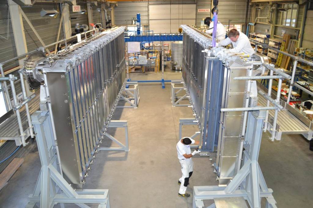
The neutralizer consists of four channels made from five copper panels, containing hydrogen or deuterium gas, through which the particle beam passes.
It works by charge exchange with gas molecules of the same type as the beam.
High-speed negative ions, colliding with the rarefied hydrogen or deuterium molecules inside the channels, lose the electron they had acquired in the source (but not their speed or energy) and become neutral.
One of the most critical aspects of the neutralizer is the cooling circuits of the copper panels, which must withstand high thermal power (up to a total of 6 MW). Its construction allows it to resist power densities up to 5 MW/m².
The neutralizer has an expected efficiency of about 50-60%, meaning only 50-60% of the ions are neutralized. The remaining 40-50% of negative ions are subsequently removed by a third component called the RID or “RESIDUAL ION DUMP”
Inside the RID, transverse electric fields are generated that can deflect the remaining negative ions after they pass through the neutralizer and attract them to the device’s lateral walls, where they remain trapped.
(Discover later below what an electric field is)
The instrument is made up of five longitudinal panels. Between each pair of panels, a constant direct voltage of up to 30 kV maximum is applied.
Given the high energy deposited, the walls must necessarily be cooled with water.
The RID is designed to absorb and dissipate a total power of about 19 MW and to withstand power densities up to 8 MW/m².
An electric charge in space generates an electric field around itself. A second charge placed within this field will experience a force from it. This force is repulsive if the two charges have the same sign, attractive otherwise.
Even a uniformly charged surface generates an electric field around itself. The RID plates are charged in such a way as to generate electric fields capable of attracting and capturing the residual hydrogen or deuterium ions still present after passing through the neutralizer, removing them almost completely.
The MITICA calorimeter is designed to intercept the high-energy beam produced by the injector, absorb all its power, and measure its parameters.
It consists of two walls of water-cooled tubes that, in ITER, through a suitable movement system, can assume two different configurations:
The calorimeter is designed to absorb beam energy up to 18 MW.
-1MV
MITICA uses a 1 million Volt (1 MVdc) direct current power supply system, which is the world’s first prototype at this voltage, power (56 MW), and size.
The system was designed and produced in collaboration with the Japanese laboratory QST and the European agency F4E.
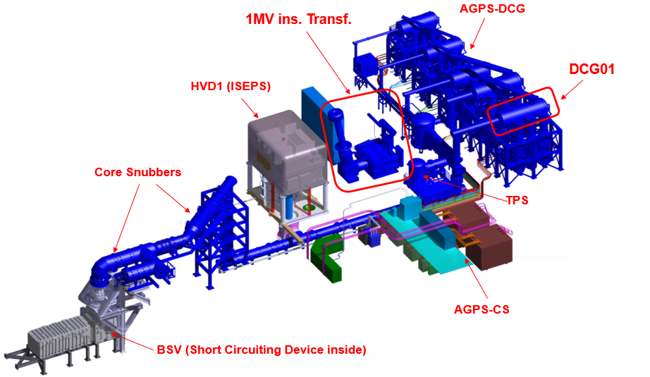
It consists of several parts (see figure below):
The one million volts supplied by the system has a negative polarity because the ion source is designed to produce negative ions, which are subsequently accelerated toward ground potential through five acceleration stages, each at 200 kV. The choice to operate with negative ions was made due to the higher efficiency of the neutralization process.
Power is the amount of energy absorbed or delivered by a system in one second. Its unit of measurement is the Watt (W).
1 Watt is equivalent to 1 Joule per second, with the joule being the unit of energy.
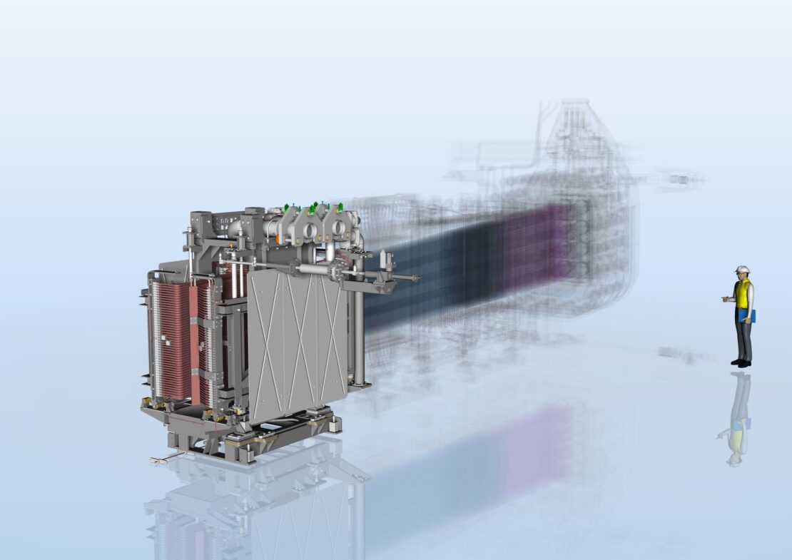
The AGPS supplies voltage to the acceleration grids. It is composed of five -200 kV DC Generators (DCGs) connected in series.
Each DCG contains a three-phase step-up transformer and a three-phase diode bridge.
The output conductors from the five DCGs pass, through SF₆-insulated lines, into an RC filter unit that filters and selects the voltages to the desired values.
A transformer is a device that operates only with alternating current, capable of transferring electrical energy from one circuit to another by changing the voltage of the alternating current passing through it.
The transformer is called single-phase if it changes the voltage applied to a single conductor (phase), and three-phase if it operates on three conductors carrying voltages that are time-shifted (out of phase) with respect to each other.
A diode is a device that allows current to flow in only one direction. It therefore enables the conversion of alternating current (AC) into direct current (DC).
A three-phase diode bridge uses six diodes to convert three-phase alternating current into direct current.
An RC filter unit is a circuit used to filter an electrical signal by selecting or attenuating certain frequencies of that signal.
To power the AGPS transformer and diode system, the AGPS control system (AGPS-CS) is used, which includes AC/DC converters and inverters.
The use of inverters at this stage allows automatic intervention in case of detection of electrical discharges between the acceleration grids (which occur during normal operation of the accelerator), by suspending the current supply within very short timescales (on the order of microseconds)
In summary:
| Component | Function |
| AGPS-CS | It draws alternating current from the power grid, converts it to direct current, and then back to alternating current (AC/DC/AC). This allows precise control of the supplied voltages and enables rapid shutdown and subsequent quick restart in case electrical discharges are detected between the acceleration grids. |
| AGPS-DCG | It steps up the voltages coming from the AGPS-CS and produces direct current to power the accelerator grids downstream of the ion source and accelerate the beam. |
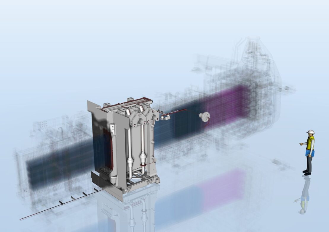
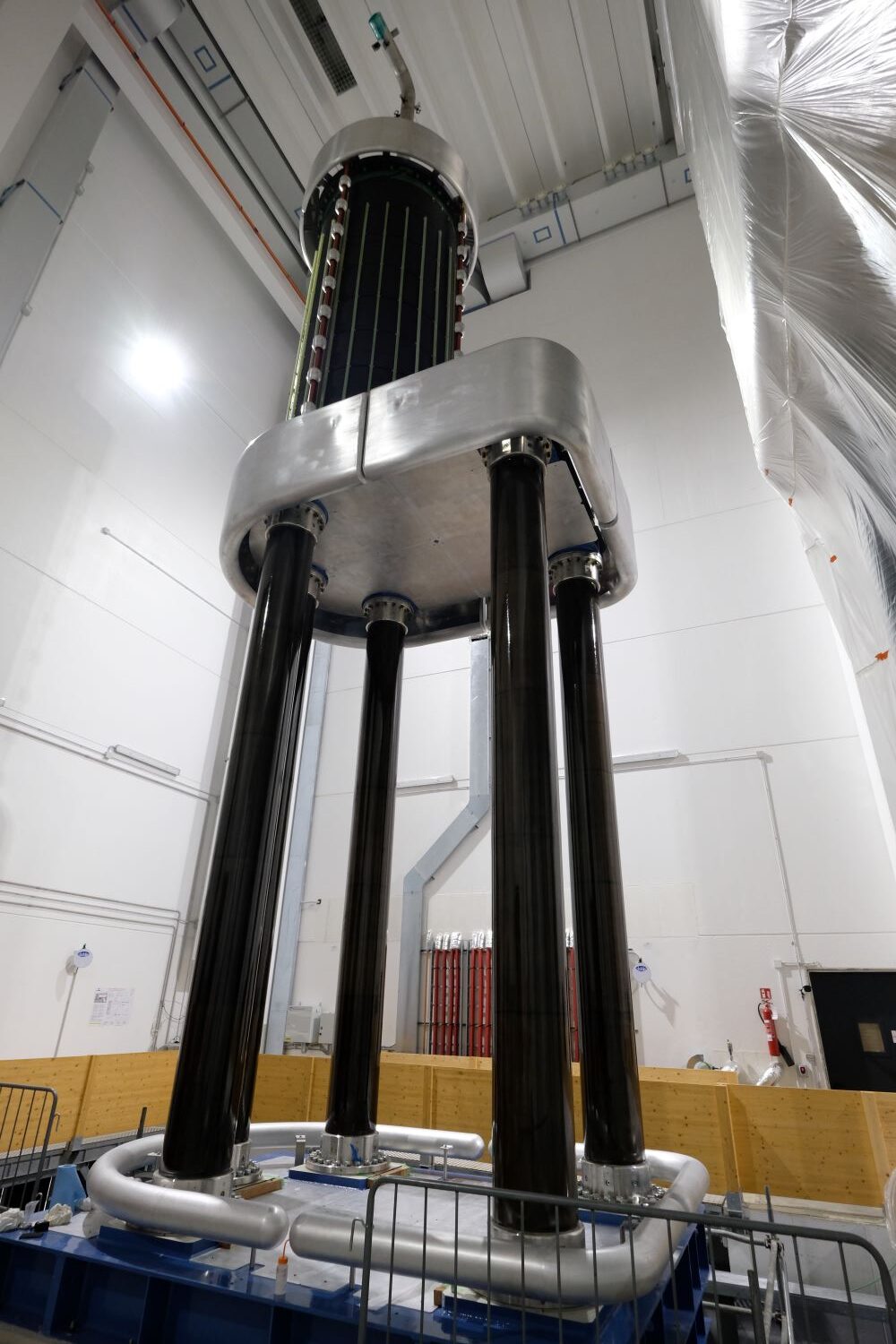
The High Voltage Deck 1 (HVD1) is an imposing Faraday cage insulated in air at -1 MV DC.
It contains the power supplies for the Negative Ion Source (ISEPS).
Measuring 12.5 meters long, 9.6 meters high, and 8.4 meters wide, it rests on insulators 6.5 meters tall that support a significant weight (about 100 tons of structure and contained equipment), ensuring electrical insulation.
-1MV
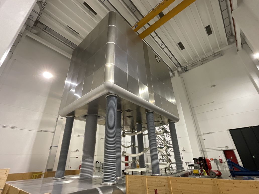
High Voltage Deck 1
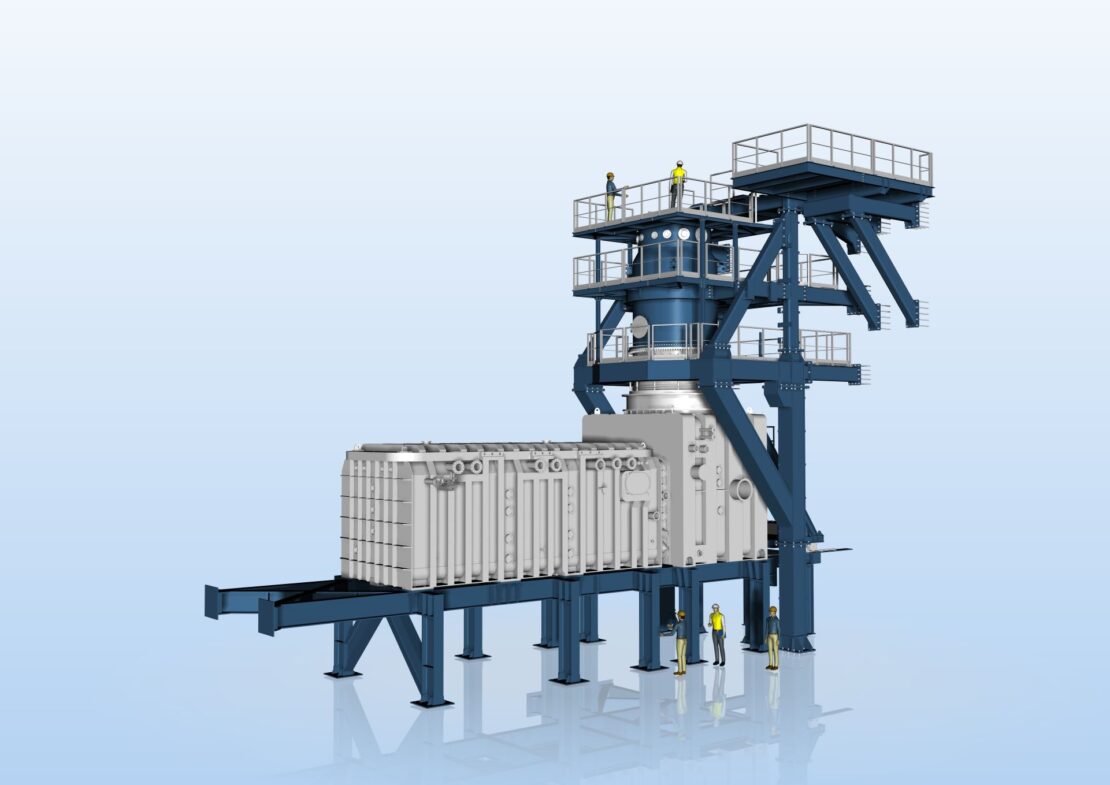
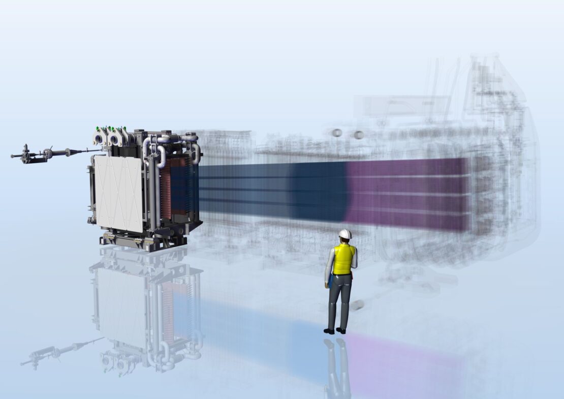
An Insulation Transformer (1 MV Insulating Transformer, see figure) powers the ISEPS inside it. Between the transformer and HVD1, a device called LCR (Inductor L, Capacitor C, and Resistor R) is connected in series to protect the transformer against overvoltages in the system (see figure).
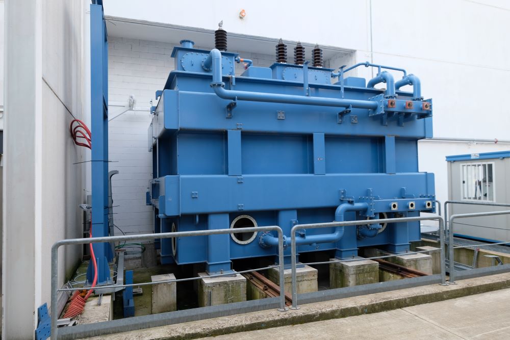
The LCR device – The isolation transformer
A Faraday cage is a hollow conductor that electrically shields its interior from any external electric field. When an external electric field acts on the Faraday cage, electric charges arrange themselves on the conductor’s surface to cancel out this field, thereby isolating the devices inside.
An insulating transformer is a device that transfers electrical energy from a primary circuit to a secondary circuit indirectly. In practice, it connects two circuits without a direct current flow between them. Thanks to this physical separation, it protects electrical equipment from possible disturbances and allows safer operation by reducing the risk of faults caused by unwanted electrical discharges.
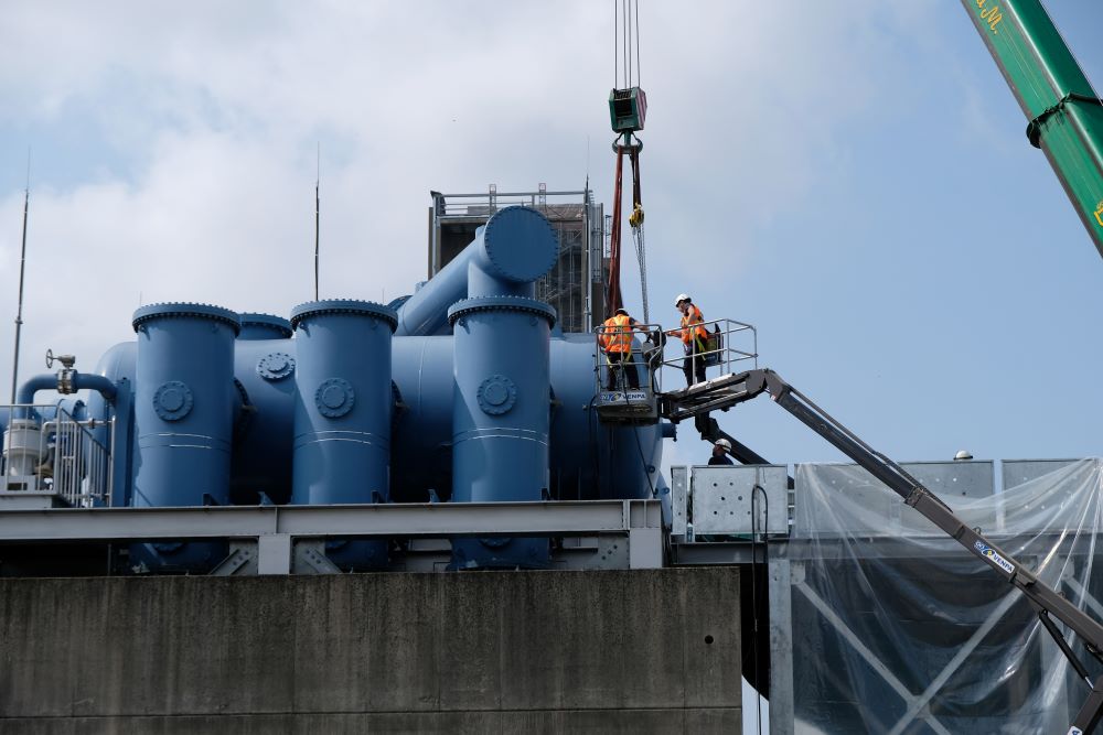
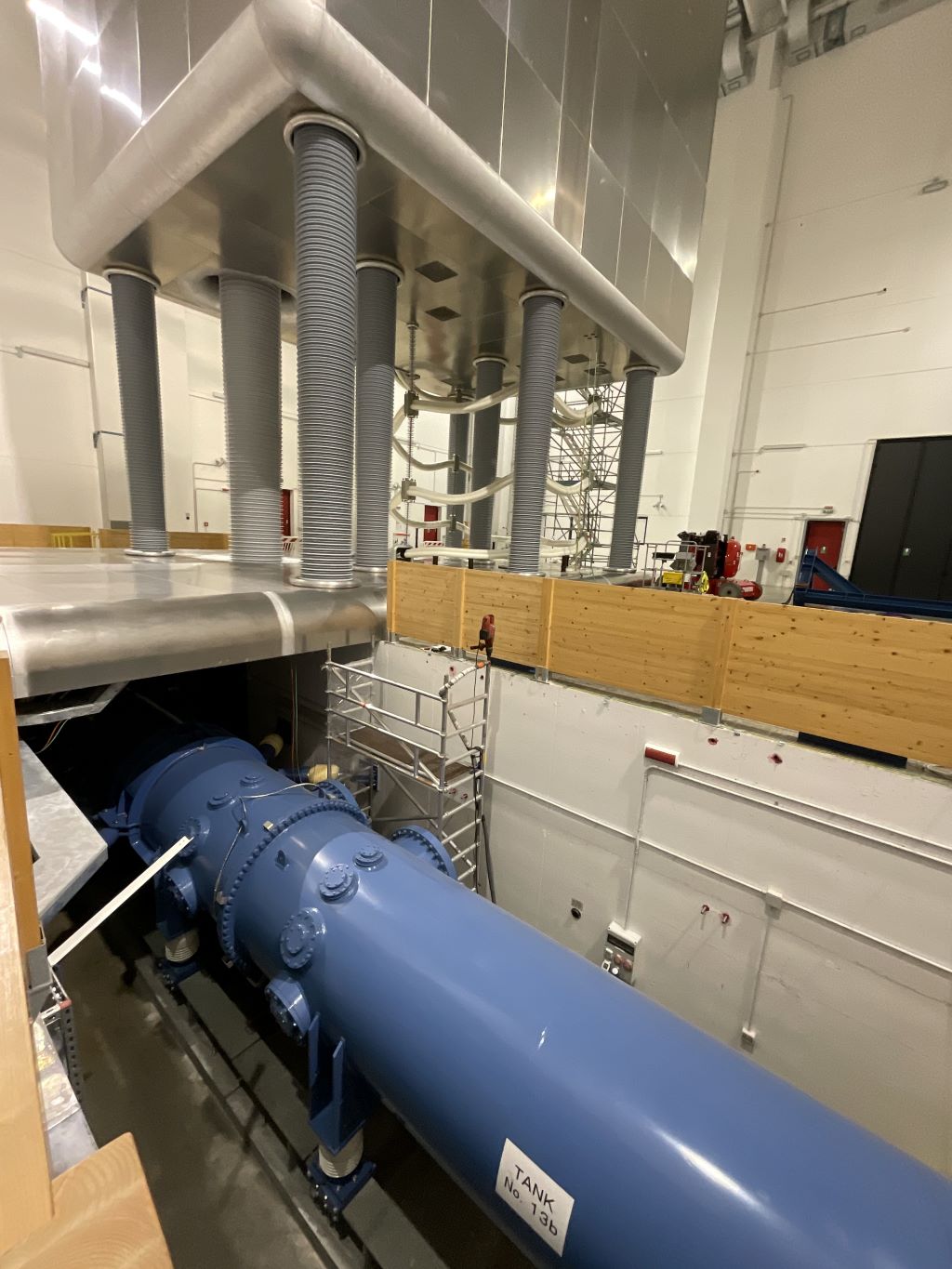
The Transmission Line (TL) connects the AGPS and ISEPS to the Beam Source installed inside MITICA’s Vessel. It is a tube about 100 meters long, with a final diameter of 3 meters, insulated with sulfur hexafluoride (SF6) gas at 6 bar pressure.
The conductors exiting the ISEPS reach the Transmission Line through an air-gas SF6 electrical feedthrough.
All this equipment, insulated in air, is installed inside a High Voltage Room with controlled environmental conditions to avoid contamination from dust
An air-gas electrical feedthrough is a component that allows electric current to pass through a wall separating two environments—one filled with air and the other with gas. The wall prevents the two gases from mixing.
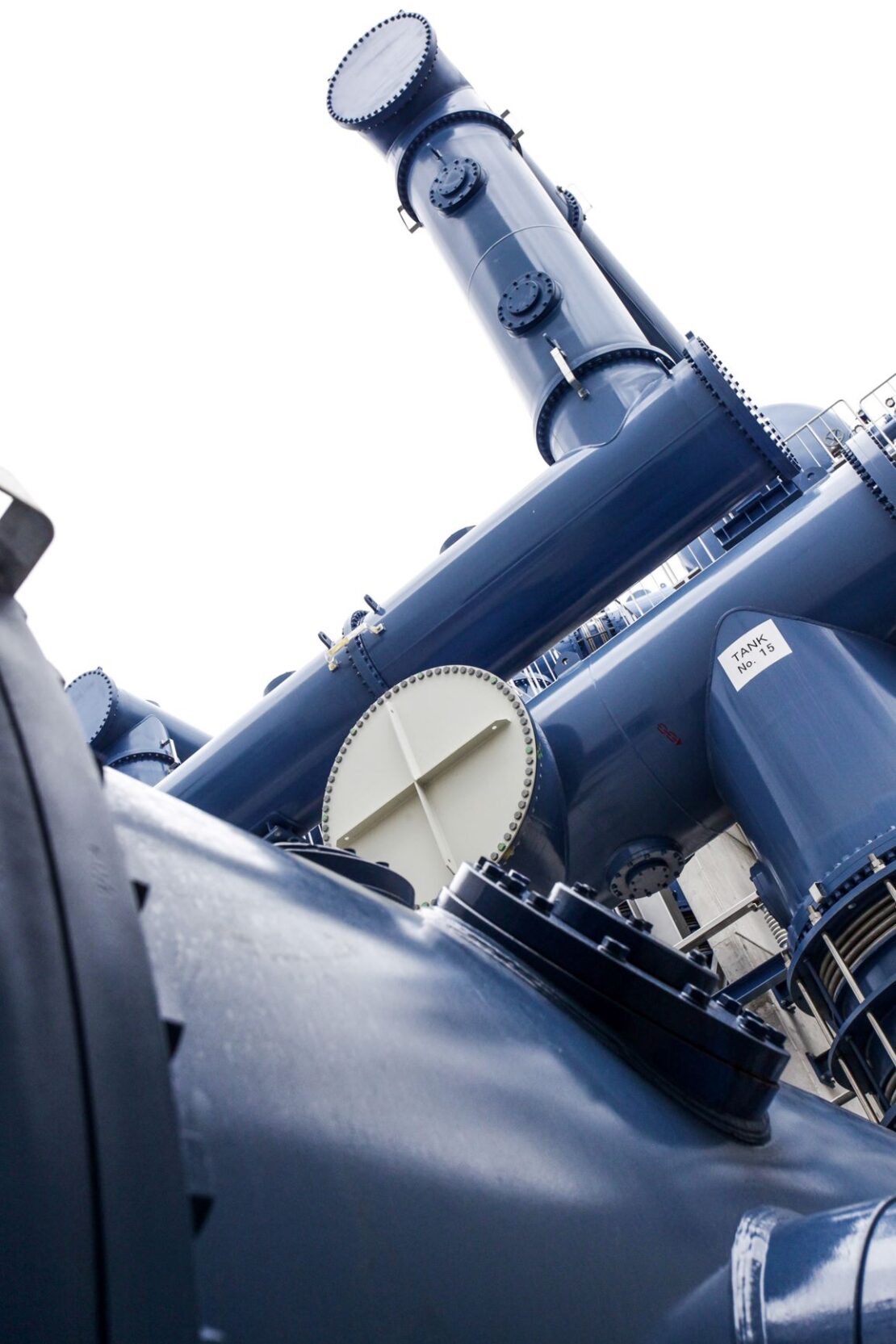
Sulfur hexafluoride (SF6) is a gas mainly used for electrical insulation in high-voltage equipment. Currently, there are no alternative gases with comparable insulating performance. It is colorless, odorless, non-flammable, and non-toxic, capable of resisting current flow. However, it is a potent greenhouse gas with a very high global warming potential.
In our laboratories, the required quantity of SF6 is stored in liquid form in storage tanks at 50 bar and moved to and from the HV components using special handling equipment. All operations strictly comply with European regulations regarding the use and management of this gas.
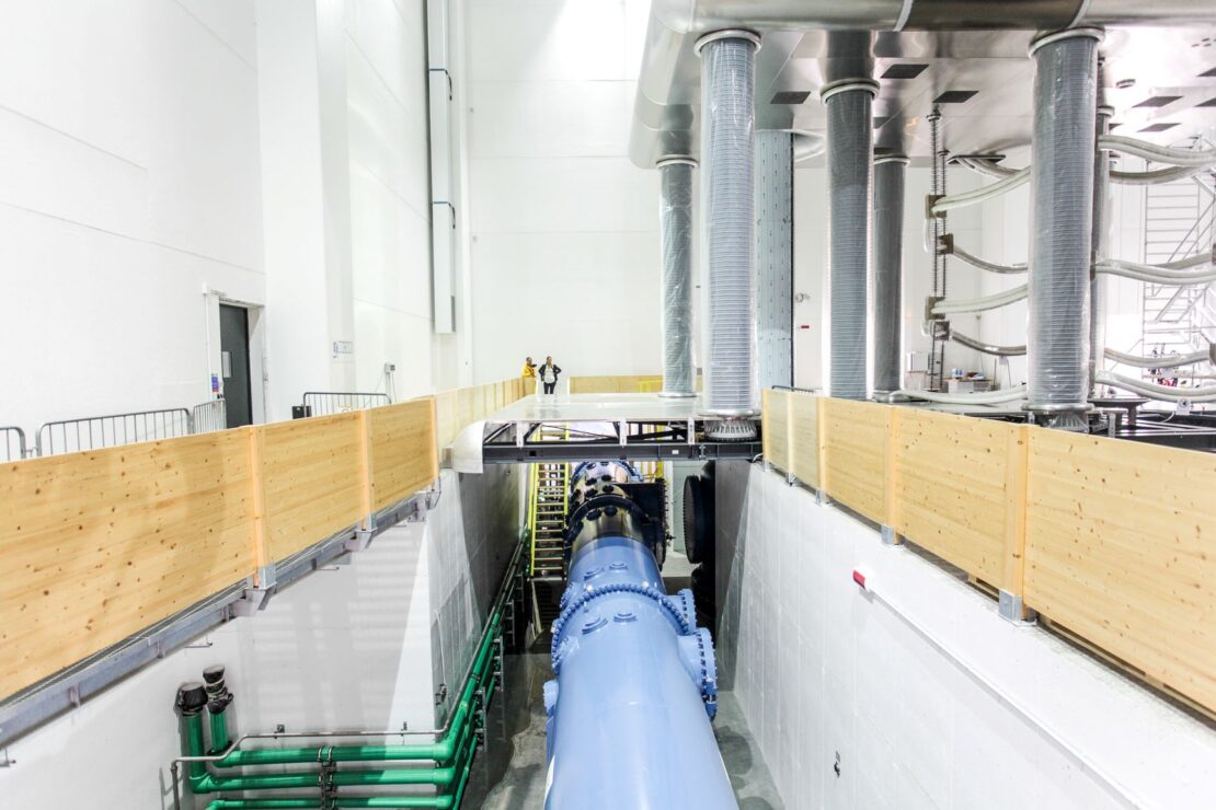
La TRANSMISSION LINE
The COOLING SYSTEM of the entire facility (MITICA and SPIDER) consists of a series of 10 primary circuits capable of dissipating the heat produced by the whole plant. The power values involved at full operation of both prototypes are enormous, around 70 MW nominal. This requires a complex cooling system.
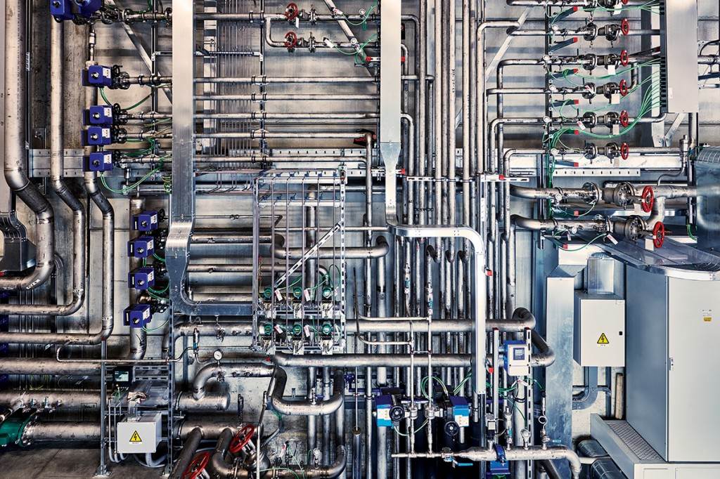
To ensure heat exchange under very high voltage conditions (up to 1 MV) and to prevent the formation of damaging electrical discharges, a specific part of the system called the Chemical Control System is used. This consists of a series of treatment processes aimed at obtaining ultrapure water that resists electrical current flow.
Ultrapure water, being highly purified, consists almost exclusively of neutral water molecules and contains no minerals or charged species capable of moving under the influence of a potential difference. For this reason, it is said to have high resistivity, meaning it allows only very weak current flow.
The Chemical Control System produces ultrapure water through various treatment methods, including ultrafiltration, electrodeionization, and reverse osmosis. These processes also allow control of the water’s acidity level (pH) and the amount of dissolved oxygen to protect the circuits from chemical corrosion.
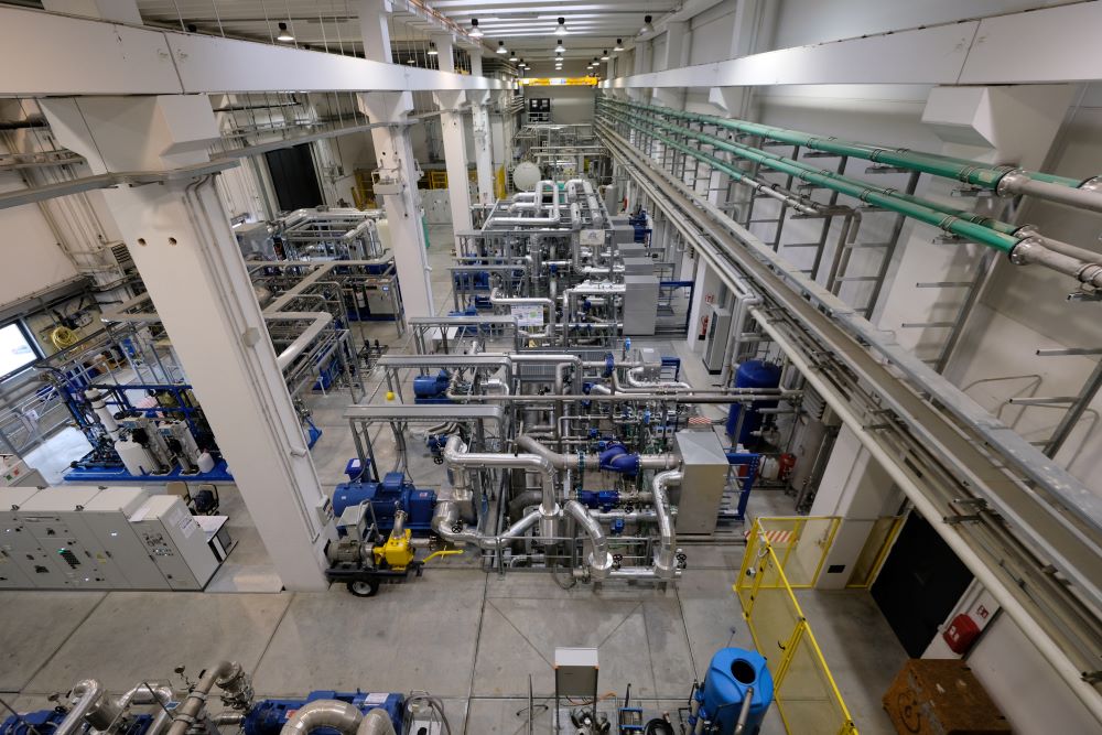
The cooling system of MITICA and SPIDER