HOW SPIDER IS MADE
what are the component parts and
what are the diagnostic systems used
Were is SPIDER housed
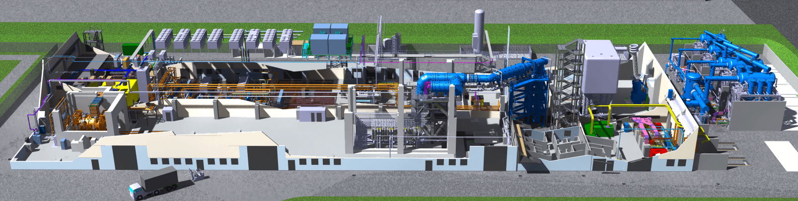
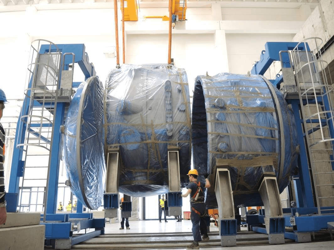
The SPIDER experiment is housed in building 1 of the NBTF plant (lower left photo) together with MITICA, the prototype of the injector (shown as gray columns in the photo). SPIDER is housed in a reinforced concrete bunker which, once closed, protects against possible neutron leaks and therefore allows safe access to building 1 even during operation of the experiment.
Where is SPIDER installed
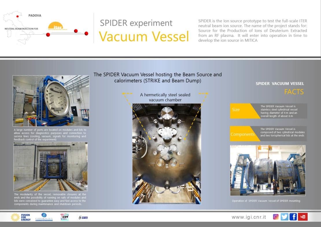
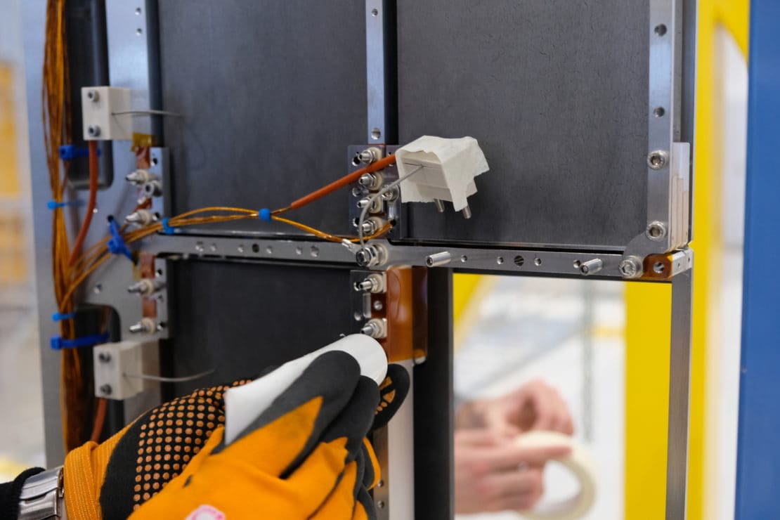
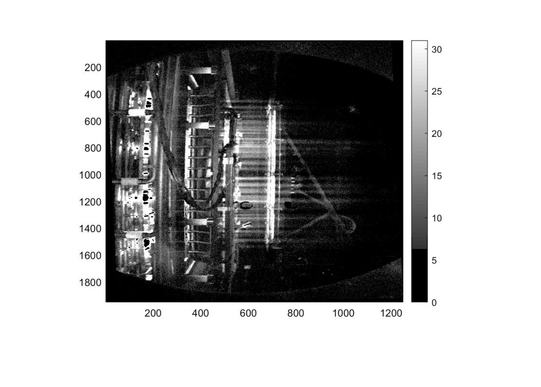
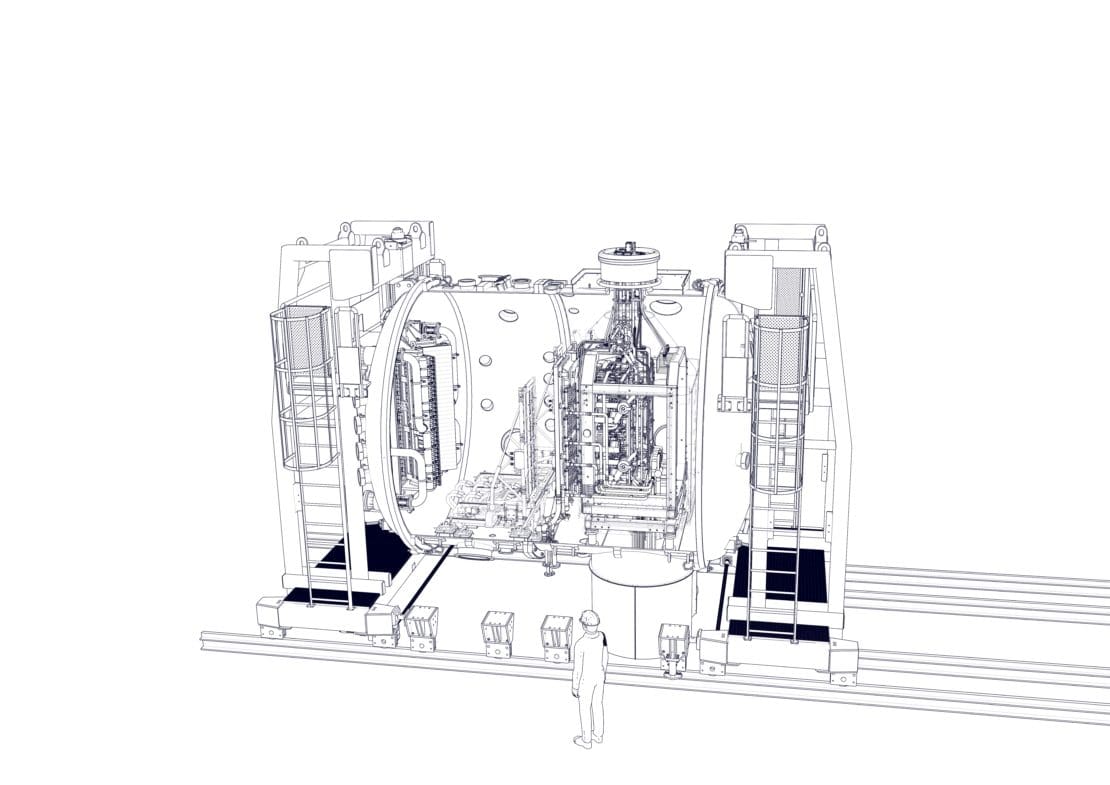
The source and the diagnostics are in turn inserted in a vacuum chamber formed by two cylindrical sections and two end-lids for a total of 4 meters in diameter and 6 meters in length, as seen in the photos below.
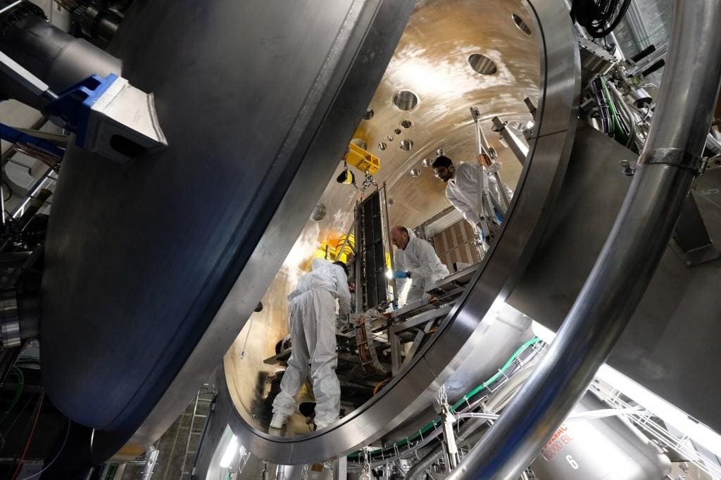
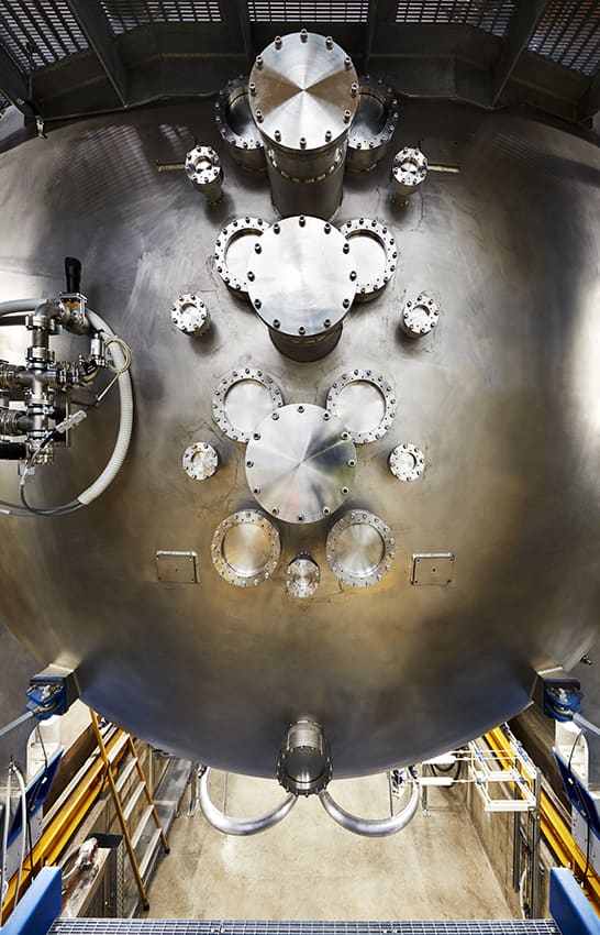
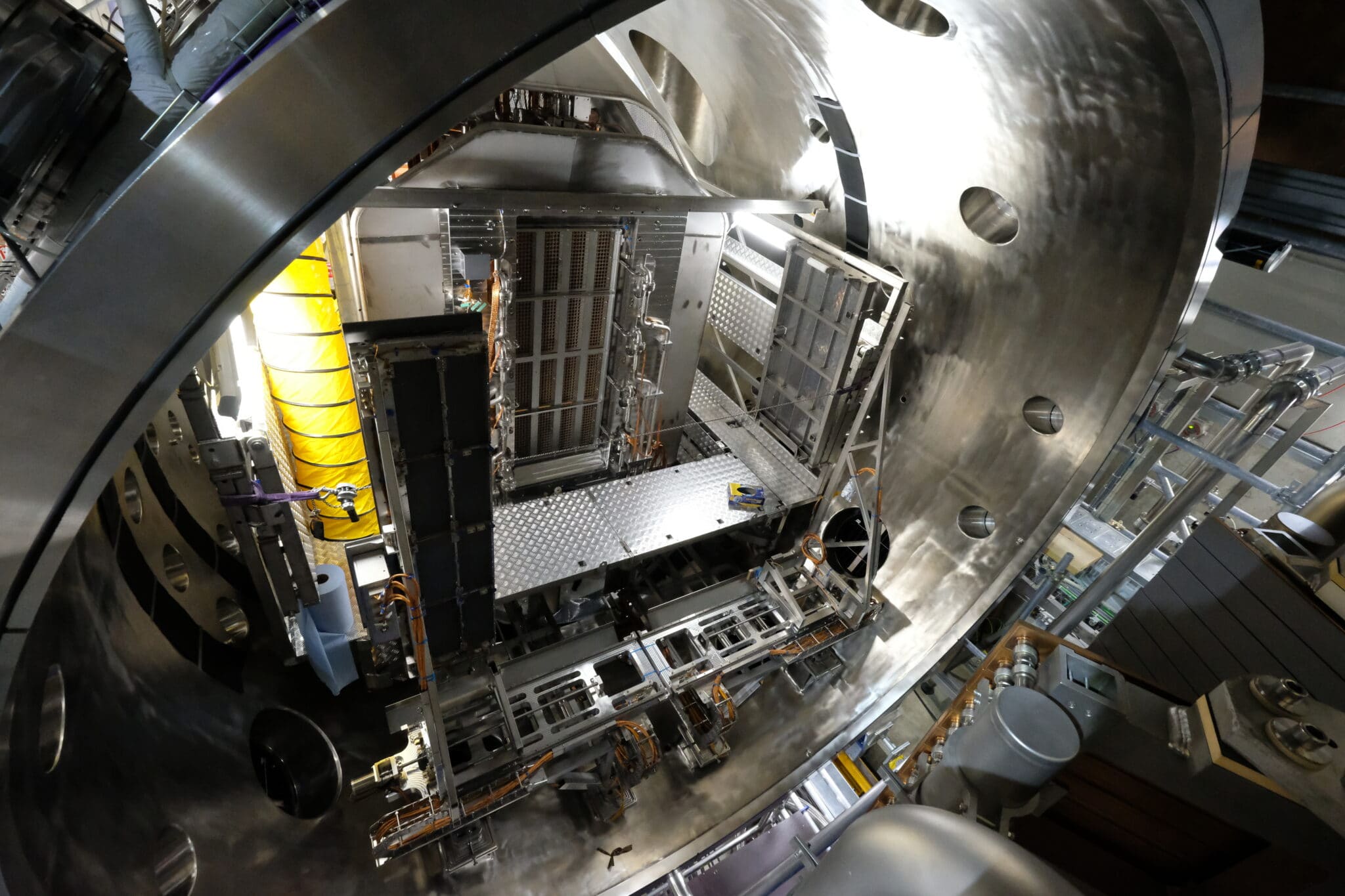
In the vacuum chamber there are many openings that allow the insertion of the diagnostic tools and to make the connections with the vacuum pumping system, the power system and the cooling system.
What are the components of SPIDER
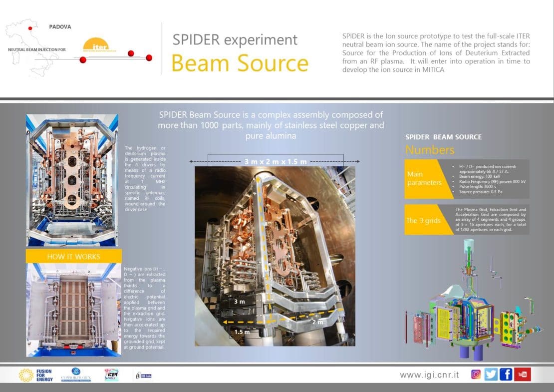
The negative ion source is made up of more than 1000 aluminium and copper parts, and is composed of a container with 8 antennas in which the plasma is formed thanks to a 1MHz radiofrequency current and by 3 plasma and extraction grids of negative ions.
Negative ions are extracted from the plasma by the electrical potential difference of the plasma grid and then accelerated by passing through the earth grid.
More specifically, the first grid is called the “plasma grid” and, in conjunction with the use of Cesium, it selects the negative particles.
The second grid or “extraction grid” magnetically deflects the electrons allowing the negative ions to continue their journey.
The last grid or “grounded grid” accelerates the ions in a beam that is intercepted by a calorimeter (which absorbs the power and allows energy measurements).
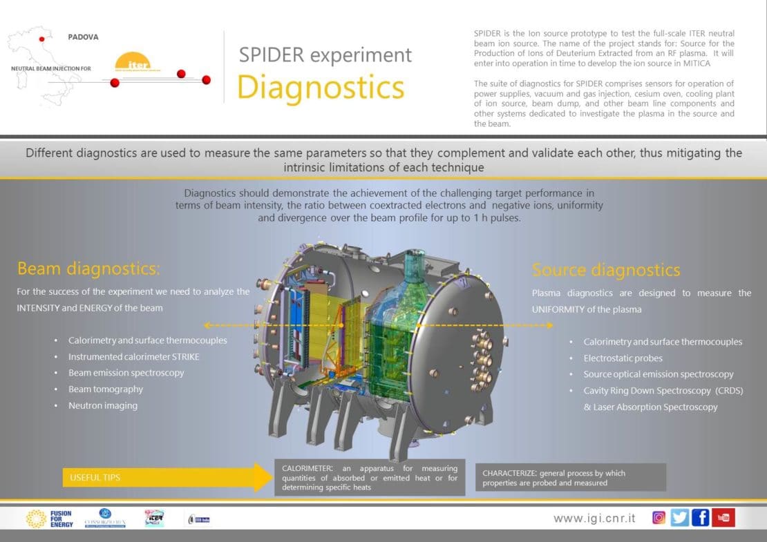
SPIDER diagnostics systems
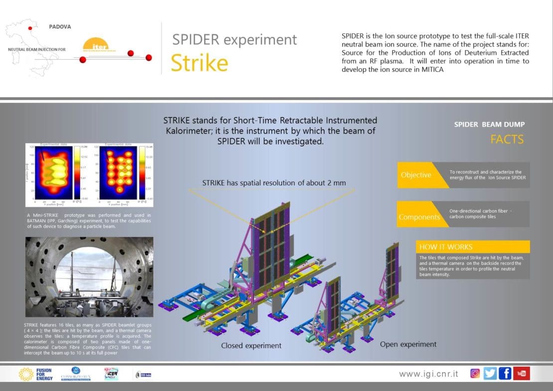
Given the importance of the measurements, TWO CALORIMETERS are provided in SPIDER: STRIKE and the BEAM DUMP, the combination of which allows you to explore very different operating conditions.
STRIKE is a high resolution calorimeter, which allows measurements to be made with the precision of a few millimeters (about 3mm), however it is not able to operate in impulses lasting more than a few seconds as it is not cooled.
In more detail, STRIKE is composed of two mobile panels of graphite fiber tiles that can be moved in a transverse position, in and out of the beam path.
When the panels are closed, they intercept the beam; the absorbed heat is transmitted through the fibers on the back of the tiles and, by means of infrared cameras, it is possible to reconstruct the heat map of the beam with high precision.
STRIKE is the main diagnostic system of SPIDER, designed to characterize the negative ion beam in terms of uniformity and divergence.
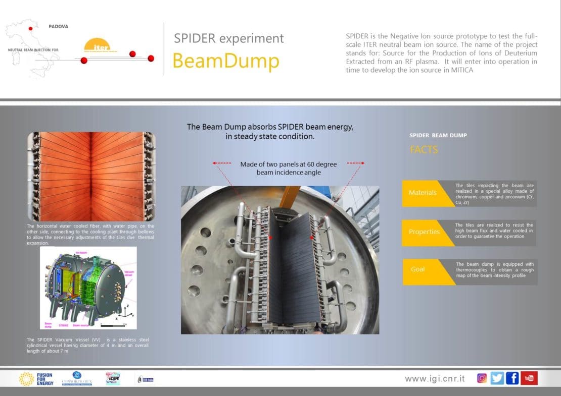
The Beam Dump is a water-cooled calorimeter and is therefore capable of absorbing full beam power in steady state. It is equipped with thermocouples for calorimetric measurements.
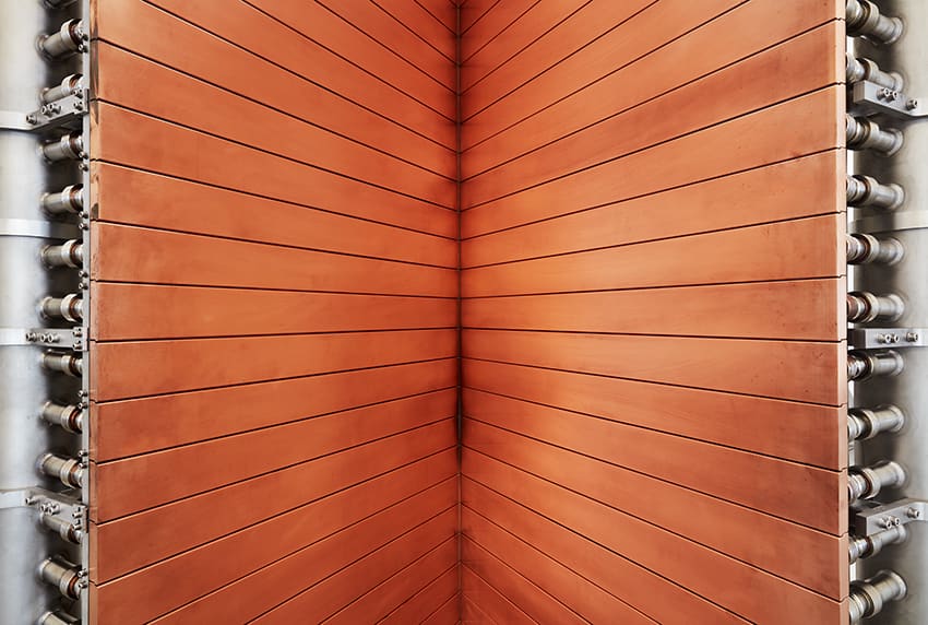
The Beam Dump consists of two panels with a 60 degree angle of incidence. On its rear-side run the pipes of the cooling system, constructed in such a way as to allow the thermal expansion of the tiles of the calorimeter. The shingles are made of a special alloy of chromium, copper and zinc to withstand high temperatures.
The Beam Dump is placed after Strike and becomes operational only when the STRIKE panels are open. Unlike STRIKE, the resolution is only a few centimeters, but it can operate at full power and for long pulses.
Other diagnostics systems of SPIDER
The characterization of the negative ion beam and the evaluation of the functioning of the SPIDER components requires additional diagnostic systems.
For beam intensity and energy analysis:
To measure plasma uniformity:
In this short video, Dr. Marco Barbisan tells us how the Cavity Ring Down Spectroscopy diagnostic works, used to measure how many negative ions are generated in SPIDER.
Leave your comment on the
Consorzio RFX Youtube channel
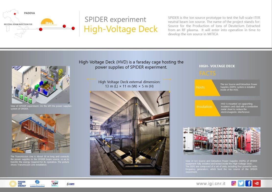
The SPIDER power supply system
The SPIDER power supply system consists of three Indian-supplied transformers and a High Voltage Deck. This system carries 100kV of voltage in the SPIDER experiment.
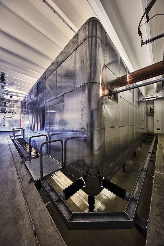
The High Voltage Deck is a large faraday cage 13 meters long, 5 meters high and 11 meters wide, resting on insulators that protect it from seismic risk.
The power supply system is placed in a room adjacent to the experiment and is connected to it by a 30 meter long copper transmission line.
The SPIDER cooling system
An entire building is dedicated to the cooling system of SPIDER and MITICA. The system is capable of dissipating up to 70 MW of power and is divided into 3 circuits.
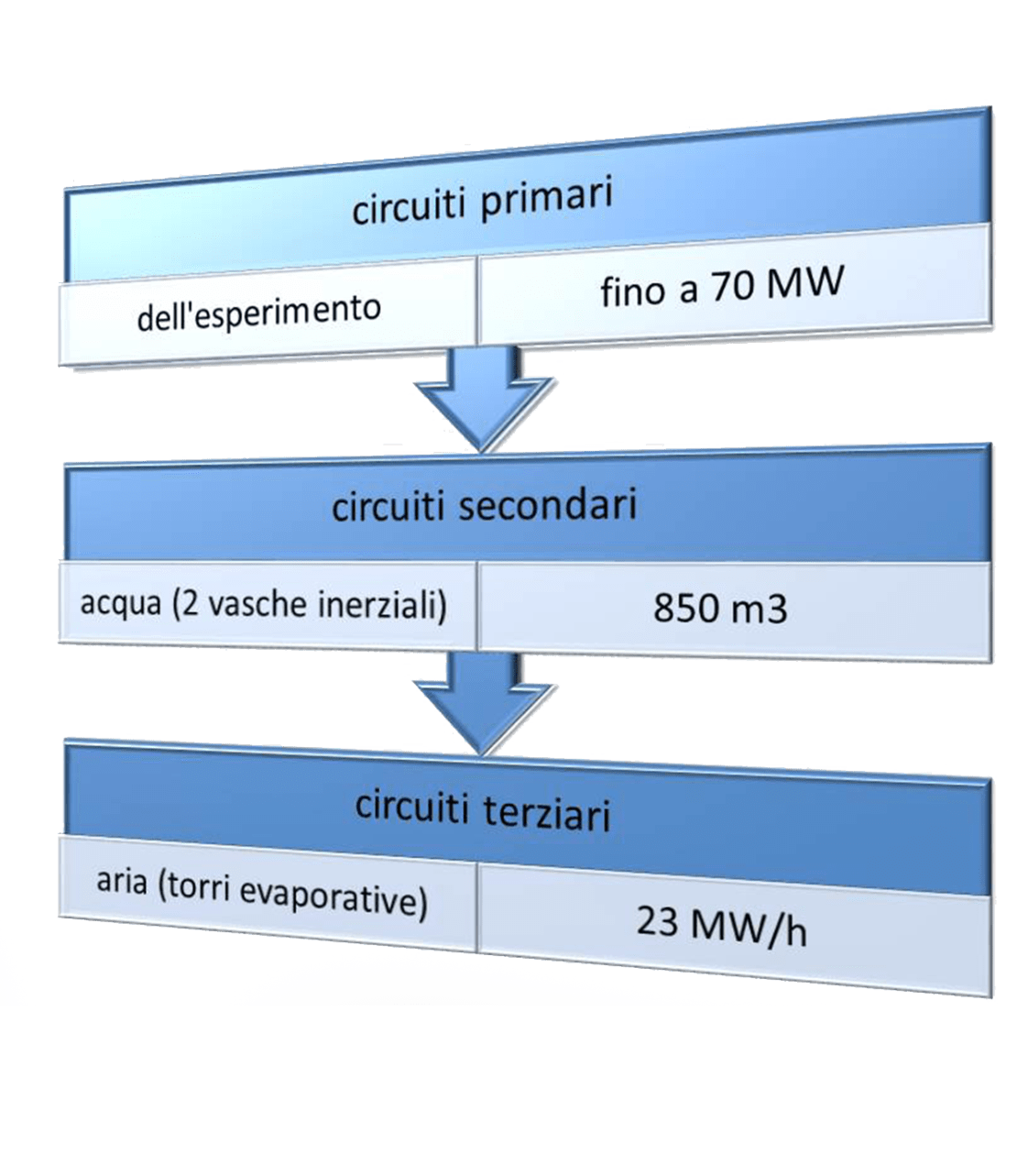
The primary circuit is in direct contact with the components of the very high voltage experiment. To avoid the risk of transporting electricity as well as heat, ultra-pure water is used which is a bad conductor unlike normal or sea water.
The secondary circuit conducts the heat in two large tanks, of 315 m3 and 545 m3, in the basement of the building, where it is stored and slowly released to the third system.
The tertiary circuit is composed of evaporation towers that very gradually release the heat stored in the tanks of the second system into the environment.
THE PHYSICS of the negative ion source
The negative particles are extracted via the voltage (up to 12 kV) created between the grids closest to the plasma (the plasma and extraction grid). The voltage penetrates the plasma behind the grids, pushing the negative particles inside the grids.
At this point, the negative particles are faced with another important step: at the level of the extraction grid permanent magnets deflect the electrons (smaller than the negative ions) without affecting the trajectory of the negative hydrogen ions (heavier) who continue their race towards the earth grid.
It should not be forgotten that the displacement of the negative hydrogen ions and their acceleration always occurs thanks to the voltage applied between the grids.
The voltage applied between the extraction grid and the earth grid, fixed at 100 kV, is essential to accelerate the beam. The negative hydrogen ions subjected to this voltage are accelerated as they leave the ground grid and hit the STRIKE diagnostics, capable of determining the “goodness” of the beam obtained.
The acceleration of the negative hydrogen ions can be calculated by adding the voltage applied between the grids, at maximum power so they will have an energy of 112 keV.
How do we know that the experiment worked? Thanks to the diagnostics.
In this case we used 4 diagnostics:
The visible camera that showed the bundles, with a view perpendicular to the grids.
STRIKE detected the heat of the beam that hit it by means of the infrared camera which read and “captured” the data collected on its rear-side.
The current was detected by the Extraction Grid Power Supply which records the electrical input and output signals, allowing us to know the current of the beam.
BES (Beam Extraction Spetroscopy) diagnostics confirmed that the negative particles forming the beam are H-, thanks to spectroscopy that measured a peak at 65670 Angstrom typical of this chemical species.
If you want to know more, download our datasheets