HOW IS MITICA MADE
what are its various components
and what are the diagnostic systems it uses
Where is MITICA housed?
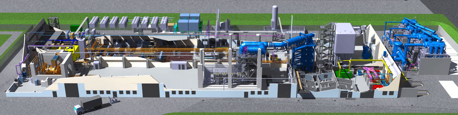
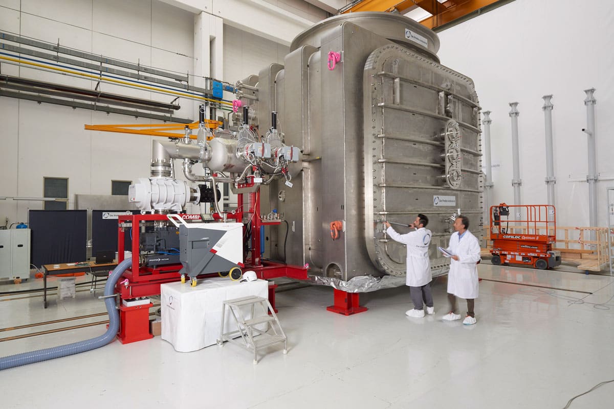
The prototype of the ITER neutral particle injector is housed in building 1 of the NBTF plant (photo, bottom center in gray) together with SPIDER, the prototype negative ion source (in the photo represented on the left in gold). MITICA is housed in a reinforced concrete bunker with 180 cm thick walls, which, once closed, protects from neutron radiation and X-rays produced by the injector and therefore allows safe access to building 1 even during operation.
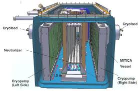
Inside the MITICA bunker
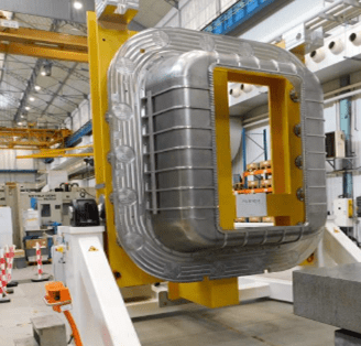
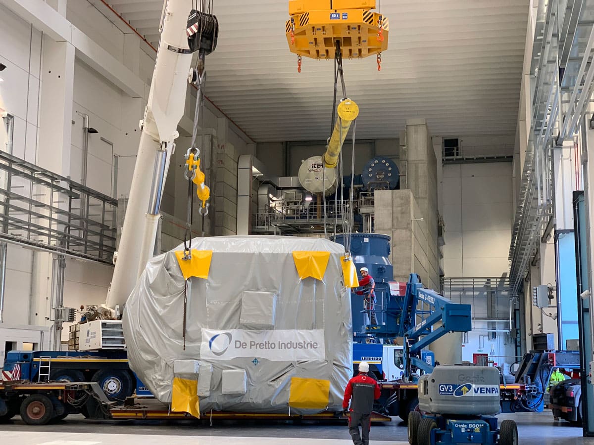
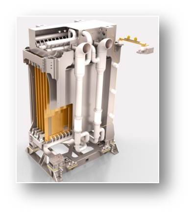
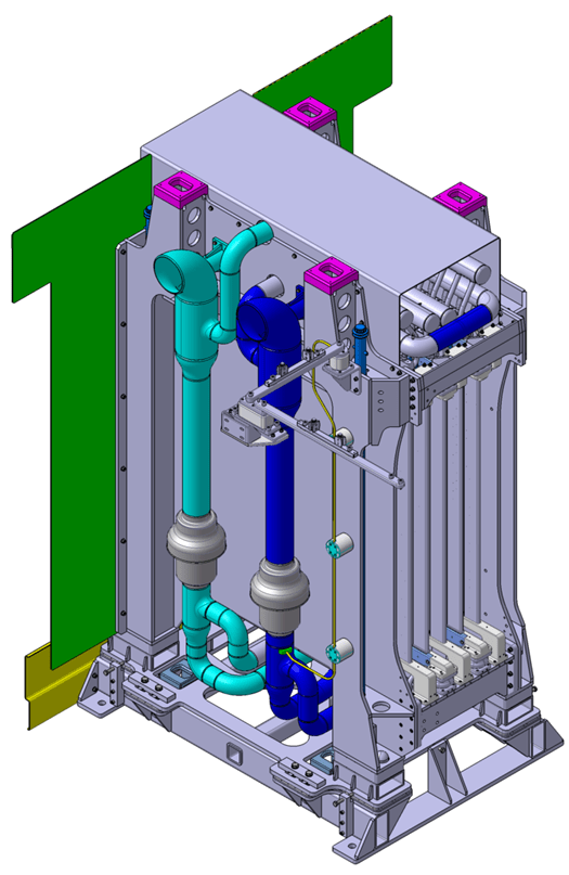
The injector prototype includes the beam source (ion source and acceleration grids), the neutralizer and the Residual Ion Dump and the Calorimeter, all installed inside a vacuum chamber formed by two 304L stainless steel modules . The first module, the Beam Source Vessel (BSV), is a 5 x 5 x 5 meter cube shape weighing 67 tones and will house the beam source.
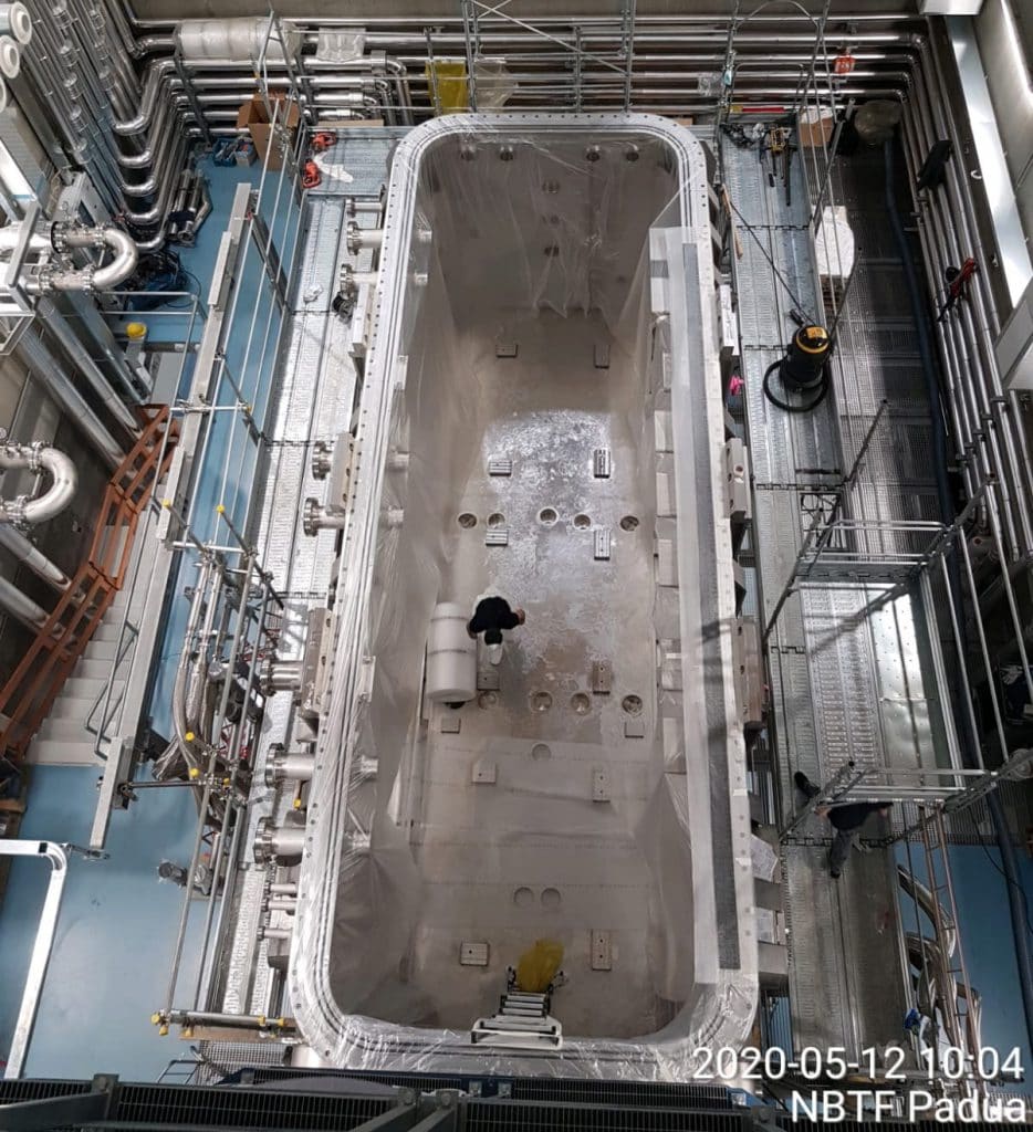
The second module is the Beam Line Vessel (BLV), which is 4.5 meters high by 4.5 meters wide by 11 meters long with a mass of 76 tons, and will contain the components along the beam line and the cryopumps, as we can see in the photos.
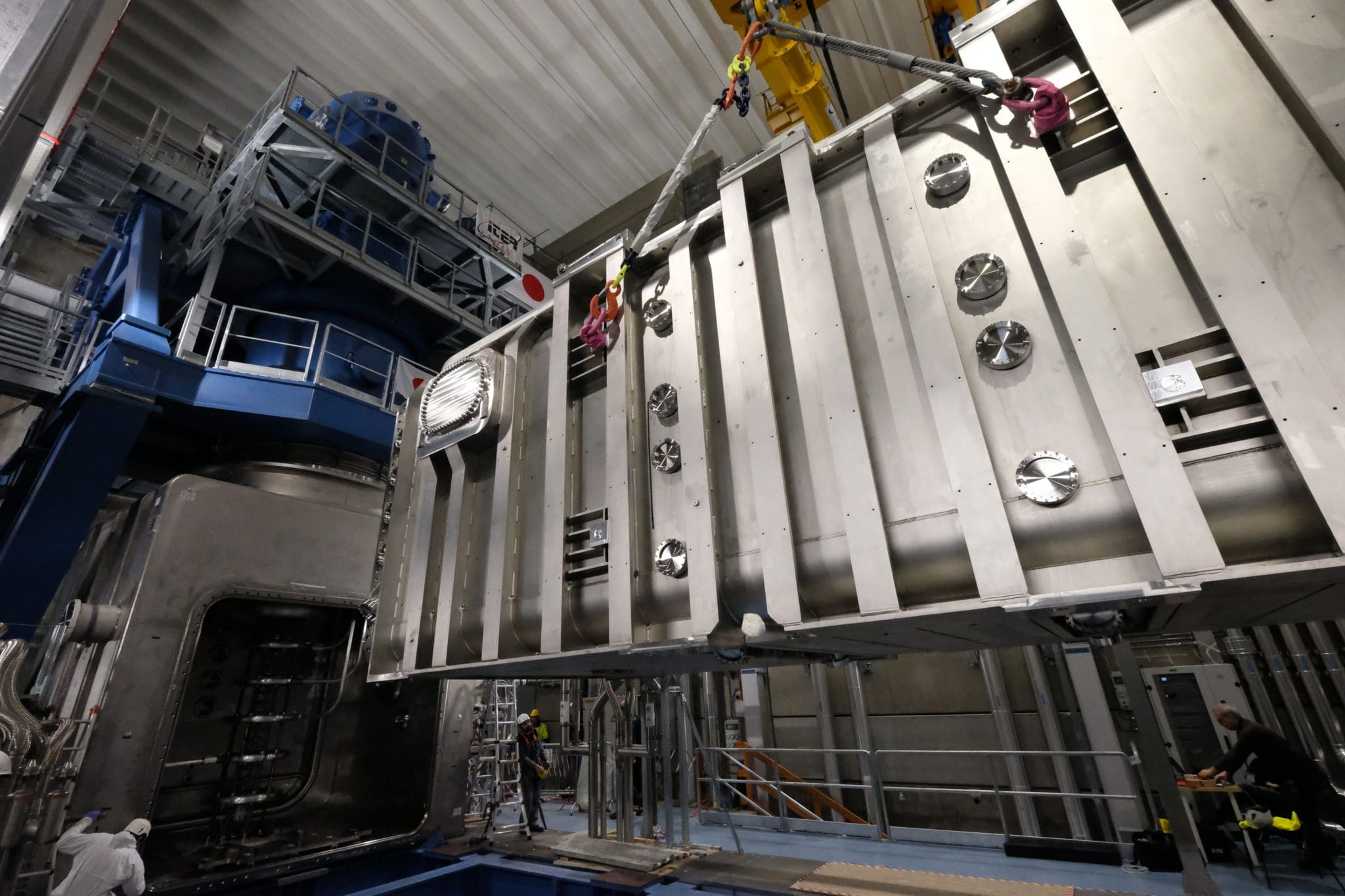
On the vacuum chamber you can see the openings that allow for the insertion of the diagnostic tools and to make the connections with the system that keeps the structure under vacuum, along with the power supply and the cooling system.
The components of MITICA
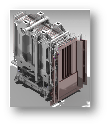
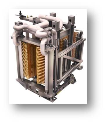
The Beam Source
The MITICA Beam Source operates at 1MV and is composed of the negative ion source and 7 grids:
designed to operate at a maximum temperature of 200 ° C
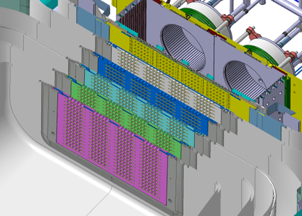
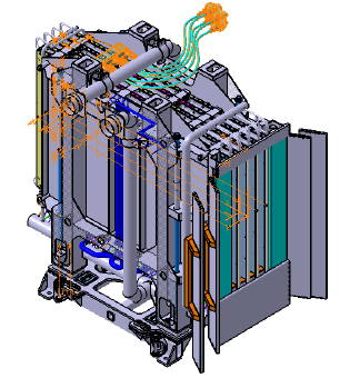
In the image: the MITICA Beam Source: the extraction drivers and the grids are highlighted
The beam source measures 3 x 3 x 4.5 meters and weighs approximately 15 tons.
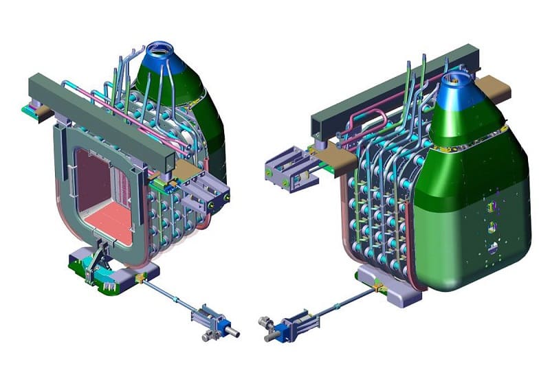
Illustrations of the MITICA Beam Source, the injector prototype made in the Neutral Beam Test Facility, at Consorzio RFX, Padua, Italy.
The generated negative ions are extracted in the space between the plasma grid and the extraction grid, and accelerated to the ground grid through five 200 kV acceleration phases, with four intermediate acceleration grids.
This system produces a 46 Amp Hydrogen ion beam or a 40 Amp Deuterium ion beam.
The Neutralizer
The neutralizer makes the negative particle beam neutral via charge exchange between the accelerated beam and a cloud of neutral gas molecules of the same type. The neutralizer consists of four channels, capable of absorbing a total power of up to 5 MW.
The neutralization efficiency of the high energy negative ion beam is around 50%, therefore a significant amount of positive and negative ions must be filtered out downstream of the neutralizer by a residual ion dump.
The Residual Ion Dump
Downstream of the neutralizer is the residual ion cleaner, or Residual Ion Dump, which is able to remove the negative and positive ions left in the beam by applying a transverse electric field that captures charged particles, but has no effect on the neutralized beam particles. The instrument consists of five longitudinal panels. A direct current voltage of up to 30 kV is applied between each pair of panels.
The residual ion cleaner is designed to absorb and remove a total power of approximately 19 MW and to withstand power densities up to 8 MW.
The Calorimeter
The Calorimeter consists of two walls of water-cooled pipes which with an appropriate handling system can assume a closed “V-shape” configuration and in this case intercept the neutral beam, or remain open in the parallel position letting the beam exit undisturbed from the injector.
When the calorimeter is closed, it absorbs all the power of the beam and allows for power measurements. When open, the injector delivers its plasma power.
The calorimeter is designed to absorb the beam energy, up to 18 MW.
The MITICA power supply
MITICA è alimentata da un sistema di alimentazione a 1 MV, unico al mondo per potenza e dimensioni.
Si compone di:
5 AGDS-DC generators
a 1MV isolating transformer
the 1 MV transmission line
the AGPS conversion system
a 1MV Faraday cage which houses the power supplies of the ion source
a 1MV bushing insulator
1 MV Power supplies
click on the image to highlight the systems
The Transmission Line
The 1 MV transmission line was designed and manufactured in collaboration with the Japanese QST laboratory. At approximately 100 meters long, it connects the acceleration grid power supply system (AGPS) with the negative ion source, bringing all the diagnostic and power supply conductors of ISEPS inside its high voltage electrode.